VIRTUAL MEMORY
VIRTUAL MEMORY. Submitted by Sachin Batra and Anil Bhardwaj. Why Do We Need Virtual Memory?.

VIRTUAL MEMORY
E N D
Presentation Transcript
VIRTUAL MEMORY Submitted by Sachin Batra and Anil Bhardwaj
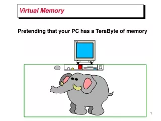
Why Do We Need Virtual Memory? Storage allocation has always been an important consideration in computer programming due to the high cost of main memory and the relative abundance and lower cost of secondary storage. Program code and data required for execution of a process must reside in main memory to be executed, but main memory may not be large enough to accommodate the needs of an entire process. Early computer programmers divided programs into sections that were transferred into main memory for a period of processing time. As the program proceeded, new sections moved into main memory and replaced sections that were not needed at that time. In this early era of computing, the programmer was responsible for devising this overlay system. As higher level languages became popular for writing more complex programs and the programmer became less familiar with the machine, the efficiency of complex programs suffered from poor overlay systems. The problem of storage allocation became more complex. This was solved by a technique called “virtual memory”. The main memory can act as a “cache” for the secondary storage. This technique is called virtual memory. There are two major motivations for virtual memory: to allow efficient and safe sharing of memory among multiple programs and to remove the programming burdens of a small, limited amount of main memory.
Definition Virtual memory is a technique that allows processes that may not be entirely in the memory to execute by means of automatic storage allocation upon request. The term virtual memory refers to the abstraction of separating logical memory--memory as seen by the process--from physical memory--memory as seen by the processor. Because of this separation, the programmer needs to be aware of only the logical memory space while the operating system maintains two or more levels of physical memory space. The virtual memory abstraction is implemented by using secondary storage to augment the processor's main memory. Data is transferred from secondary to main storage as and when necessary and the data replaced is written back to the secondary storage according to a predetermined replacement algorithm. If the data swapped is designated a fixed size, this swapping is called paging; if variable sizes are permitted and the data is split along logical lines such as subroutines or matrices, it is called segmentation. Some operating systems combine segmentation and paging
Paging Virtual memory and physical memory are broken into pages. Main memory is divided into smaller blocks of fixed size. These blocks are called page frames. Each page frame is typically 4 KB, although larger sizes are also used. The starting address of each page frame is the physical page number of that page. The location within a particular page frame, i.e. the offset from the starting address of that page, is given by page offset. A physical address consists of physical page number followed by page offset. A virtual address consists of virtual page number followed by page offset. This page offset is same as the page offset within the corresponding physical address. A virtual page is really mapped to a physical page. This mapping is a fully associative scheduling. In virtual memory, we locate page frames by using a table that indexes the main memory. This structure is called a page table or address space. A page table, which resides in main memory, is indexed with the virtual page number from the virtual address and contains the corresponding physical page number. Each program has it’s own page table, which maps the virtual address space of that program to main memory.To indicate the location of the page table in memory, the hardware includes a register that points to the start of the page table, this is called the page table register. The page table register points to the page table of the currently active program or process. Since a whole page is loaded into main memory , paging also makes use of spatial locality to reduce page faults and misses.. With virtual memory the CPU produces a virtual address which is translated by a combination of hardware and software to a physical address, which in turn can be used to access main memory.
The diagram illustrates that a program generated address ( 1 ) or "logical address" consisting of a logical page number plus the location within that page (x) must be interpreted or "mapped" onto an actual (physical) main memory address by the operating system using an address translation function or mapper ( 2 ). If the page is present in the main memory, the mapper substitutes the physical page frame number for the logical number ( 3 ). If the mapper detects that the page requested is not present in main memory, a fault occurs and the page must be read into a frame in main memory from secondary storage ( 4 , 5 ).
The page table is indexed with the virtual page number, to obtain the corresponding portion of the physical address. The starting address of the page table is given by the page table pointer. In the above figure the page size is 212 bytes, or 4 KB. The virtual address space is 232 bytes, or 4 GB, and the physical address space is 230 bytes,which allows main memory of up to 1 GB. The number of entries in the page table is then 220 . The valid bit for each entry indicates, whether the mapping is legal. If it is off, then the page is not present in memory.
The page table maps each page in virtual memory to either a page in main memory or a page stored on the disk, which is the next level in the hierarchy. Page Fault: If the valid bit for the virtual page is off, a page fault occurs. Then the operating system is given control. This transfer is done with the exception mechanism. Once the operating system gets control it must find the page in the next level of hierarchy. To find the virtual page on the disk, operating system uses either a single page table containing both physical page numbers and disk addresses or a auxiliary data structure containing only the disk addresses.
The operating system also creates a data structure that tracks which processes and which virtual addresses use each physical page. When a page fault occurs, if all pages in the main memory are in use, the operating system chooses a page to replace on the basis of least recently used replacement scheme(LRU). LRU makes use of temporal locality. If the page to replaced has been overwritten, then it has to be written back to the disk. To determine if a page has been overwritten, a dirty bit is used. For each page number, page table has a dirty bit. When a particular page is overwritten, it’s dirty bit in the page table is set. If the dirty bit is set,the page to be replaced is first written back to either the main memory or a write back buffer. After this the new page is loaded into the main memory.
Segmentation It is very common for the size of program modules to change dynamically. For instance, the programmer may have no knowledge of the size of a growing data structure. If a single address space is used, as in the paging form of virtual memory, once the memory is allocated for modules they cannot vary in size. This restriction results in either wastage or shortage of memory. To avoid the above problem, some computer systems are provided with many independent address spaces , which are variable in size. Each of these address spaces is called a segment and the scheme implementing these segments is called segmentation. In segmentation the address consists of two parts segment number and segment offset. The segment register is mapped to a physical address, and the offset is added to find the actual physical address.The address of each segment begins with 0 and segments may be compiled separately. Because the segment can vary in size, a bounds check is also needed to make sure that the offset is within the segment. In addition, segments may be protected individually or shared between processes. However, segmentation is not transparent to the programmer like paging. The programmer is involved in establishing and maintaining the segments. A logical address space is a collection of segments. Each segment has a name and length. The addresses specify both the segment name and the offset within the segment. The user has to specify both unlike paging where user specified only a single address, which was partitioned by the hardware into page number and an offset, all invisible to the programmer. Segments are numbered and are referred to by a segment number, rather than by a segment name. A logical address consists of a tuple: <segment-number, offset>. Mapping of user defined address into physical address is effected by a segment table. Each entry of the segment table has a segment base and a segment limit. The segment base contains the starting physical address where the segment resides in memory , whereas the segment limit specifies the length of the segment.
Following picture is an example of segmentation. It shows 5 segments numbered from 0 through 4. The segments are stored in physical memory as shown. The segment table has a separate entry for each segment, giving the beginning address of the segment in the physical memory(the base) and the length of that segment(the limit). For example segment 2 is 400 bytes long and begins at location 4300. Thus, a reference to byte 53 of segment 2 is mapped onto location 4300 + 53 = 4353. A reference to segment 3, byte 852, is mapped to 3200(the base of segment 3) + 852 = 4052. A reference to byte 1222 of segment 0 would result in a trap to the operating system, as this segment is only 1000 bytes long.
Segment table is storedin main memory. A segment-table base register (STBR) points to the segment table. Also, because the number of segments used by a program may vary widely, a segment-table length register (STLR) is used. For a logical address (s,d), we first check that the segment number s is legal (that is , s< STLR). Then, we add the segment number to the STBR, resulting in the address (STBR + s) in memory of the segment-table entry. This entry is read from memory and we proceed as before: Check the offset against the segment length and compute the physical address of the desired byte as the sum of the segment base and offset. Protection and Sharing A particular advantage of segmentation is the association of protection with the segments. Because segments represent a semantically defined portion of the program, it is likely that all entries in the segment will be used the same way. Hence we have segments that are instructions, whereas other segments that are data. Instructions are non-self modifying, so instruction segments can be defined as read-only or execute-only. The memory-mapping hardware will check the protection bits associated with each segment-table entry to prevent illegal access to memory, such as attempts to write into a read-only segment, or to use an execute-only segment as data. By placing an array in it’s own segment, the memory- management hardware will automatically check that array indexes are legal and do not stray outside the array boundaries. Thus many common program errors will be detected by the hardware before they can cause serious damage. Another advantage of segmentation involves the sharing of code or data. Each process has a segment table associated with it, which the dispatcher uses to define the hardware segment table when this process is given the CPU. Segments are shared when entries in the segment tables of two different processes point to the same physical locations.
The sharing occurs at the segment level. Thus, any information can be shared if it is defined to be a segment. Several segments can be shared, so a program composed of several segments can be shared. For example,consider the use of text editor in a time-sharing system. A complete editor might be quite large, composed of many segments. These segments can be shared among all users, limiting the physical memory needed to support editing tasks. Rather than n copies of the editor we need only one copy. For each user we still need separate, unique segments to store local variables. These segments, would not be shared.
Segmentation with Paging Some operating systems allow for the combination of segmentation with paging. If the size of a segment exceeds the size of main memory, the segment may be divided into equal size pages. The address consists of three parts: (1) segment number (2) the page within the segment and (3) the offset within the page. The segment number is used to find the segment descriptor and the address within the segment is used to find the page frame and the offset within that page.
SEGMENTATION PAGING Involves programmer Transparent to programmer Separate compiling No separate compiling Separate protection No separate protection Shared code No shared code Comparison between Paging and Segmentation
SUN SPARC The acronym SPARC stands for Scalable Processor ARChitecture. The SPARC architecture, designed by SUN Microsystems, ensures easy way of using computer systems for all types of users ranging from end users to software developers and system administrators. The SPARC architecture is derived from RISC (Reduced Instuction Set Computer) technology developed at University of California, Berkeley. The SPARC architecture and the system software are openly available to all system developers which are the building blocks for variety of computer systems ranging from laptop computers to supercomputers. The SPARC architecture is scalable across many semiconductor technologies which include CMOS, BiCMOS, ECL and Gallium Arsenide. The combination of semiconductor scalability and architectural scalability permits SPARC system to design various computer systems. SPARC CPU The SPARC CPU has Integer Unit and Floating Unit to perform corresponding calculations. The SPARC based computers have a Memory Management Unit (MMU), a large virtual address cache using 32-bit bus. The MMU architecture can be implemented as a single chip using various semiconductor technologies like CMOS, BiCMOS, ECL and GaAs. The MMU uses three levels ofpage tablesfor address translation. The page table entries are cached for translating the address quickly. The MMU has 32-bit virtual address, 36-bit physical address, page of size 4k bytes, and page level protections. The virtual address has the following format.
The lower order 12-bits of virtual address gives the offset within the physical page. For each valid virtual page in main memory there is a corresponding valid entry in page table which contains the physical page number for that virtual page. Virtual page number is replaced by the physical page number by translating the virtual address to the physical address. Mapping a virtual address requires three levels of page tables. The first and second levels contain page table descriptors which point to next level page tables. The third level page table entry points to a physical page.
Each index field provides an offset into the corresponding page table. All page tables are not required every time as virtual address space is thinly populated. If a segment of 256KB, 16MB or 4GB of linear memory is mapped with a single page table entry, the full set of page tables are not required. If for each virtual address translation required all levels of page tables, CPU memory references would become very slow. Hence page table entries are cached in MMU's page descriptor cache or PDC which is often called a TLB or Translation Lookaside Buffer. By Caching the page table entries the access time of a page table is lessened.
Contexts The SPARC MMU can retain translations for several process address spaces at the same time. This significantly improves the context switching between processes. The address space of a process is identified by a context number. The MMU manages multiple contexts including the assignment of contexts to processes, reclamation of unused contexts and the reassignment of contexts. Context numbers are used to index into the context table (Level 1- Page Table) in main memory to find the root of the page table hierarchy for a process. Page Table Descriptor A page table descriptor (PTD) contains the physical address of a page table and defines the format of entries in the context table, Level-1 and Level-2 page tables. The format of PTD, which has Page Table Pointer (PTP) and Entry Type (ET) parts, as follows:
Page Table Pointer • Page Table Pointer (PTP) is the physical address of the base of a next level page table. The page table pointed to by a PTP must be aligned on a boundary equal to the size of the page table. The size of the three levels of page tables are as follows:
Entry Type The field distinguishes a Page Table Descriptor (PTD) from a Page Table Entry (PTE). The field values and their meanings are summarized below:
Page Table Entry A page table entry (PTE) specifies the physical address as well as the permissions of a page. The PTE format is shown below.
Physical Page Number • The higher order 24 bits of the 36-bit address are used to find the physical page number. The physical page number appears on the bits 35 through 12 of the physical bus when translation completes. • Cacheable Bit (Bit 7) • If this bit is one, the page is page cacheable by an instruction and/or data chache. • Modified Bit (Bit 6) • This bit is set to one by MMU when the page is accessed for writing. • Referenced Bit (Bit 5) • This bit is set to one by MMU when the page is accessed. • Access Permissions (Bits 2 -4) • These bits indicate whether access to this page is allowed for the transaction being attempted. • Entry Type (Bits 0 - 1) • This field distinguishes a Page Table Descriptor (PTD) from a Page Table Entry (PTE).
Intel 486 In Intel486DX processor memory is divided into 8-bit, 16-bit and 32-bit quantities called byte, word and double word respectively. Words are stored in two consecutive bytes in memory following the little-endian notation as illustrated below. In little endian notation the lower order byte is stored in lower address and higher order byte is stored in higher order byte. Double words are stored with high order byte at highest byte and low order byte at lowest address. The Intel486DX processor can convert 16 or 32 bit data between the two byte orderings by using two instructions: BSWAP which handles four byte values and XCHG which handles two byte values. In addition to the above units, the processor also supports two larger units of memory: pages and segments. Segments are variable size blocks of memory whereas pages are all of equal size--usually 4K bytes. Intel486 provides maximum flexibility to the designer by allowing both paging and segmentation.
Address Spaces • Intel486 has three distinct address spaces. • logical or virtual • linear • physical • A logical address consists of two parts: selector and offset. An offset is calculated by using the contents of general purpose registers which are used in different addressing modes. Since the output of a segment register is 14 bits, there are 16K different selectors. Offset is represented by 32 bits (i.e 4 Giga bytes). Selector and offset together give 64 Tera bytes of logical address which is seen as virtual address space by the programmer. Paging Paging divides user's program into multiple pages of same size. At any instant of time, pages which are active, are kept in main memory. This is due to the fact that paging exploits the locality of reference property exhibited by the programs. The paging mechanism in Intel 80486 processor uses a two level paging scheme.
Organization of Paging in Intel 486 Paging mechanism The Intel486 uses a two level paging scheme to translate the virtual address into physical address. All page frames are of 4K bytes which simplifies allocation and reallocation of memory. The linear address consists of three parts: Bits 0 - 11 OFFSET used to calculate the offset within the page frame Bits 12 - 21 LD1 used to locate the page frame Bits 22 - 31 LD2 used as an index for the top level page table (page directory) • Page Directory • The page directory is 4K bytes long and allows up to 1024 page directory entries; each entry is a double word. An entry contains • the address of the next level table • the page table • the information about the page table • The higher order 10 bits indicate the correct page directory entry.
Page Tables Each page table holds up to 1024 page table entries. Each page table entry contains the starting address of the page frame and statistical information. Address bits 12-21 are used to select the page table entry. The higher order 20 bits are used to find the actual physical address. Page Directory/Table Entries The lower order 12 bits of the page directory or table entries contain statistical information about page tables or pages respectively. The P bit set to 0 indicates that the entry can not be used for address translation; whereas P = 1 indicates that the address can be used for translation. Bit 5 is set by the microprocessor for both types of entries before a read/write access occurs to an address covered by the entry. The "dirty bit" (Bit 6) is set to 1 before the contents corresponding to the page table are modified. The bits 9, 10 and 11 are reserved for operating system to keep track of the "age" of the page in memory or when it was last referenced which is used in page replacement algorithms. Translation Lookaside Buffer The Intel486 DX microprocessor supports dynamic paged virtual memory. Since two level paging is implemented, address translation at two levels would considerably degrade the performance. To overcome this problem, the processor uses a cache memory which keeps track of most recently used pages. This cache is called Translation Lookaside Buffer. Each of the 32 entries of the Translation Lookaside buffer points a (page, page frame) pair.
<> • Segmentation in Intel486 • In addition to paging, Intel486 DX supports the segmentation method of memory management. The address translation mechanism is as follows: the 48 bit logical address consists of two parts: • Bits 47 - 32 segment base address • Bits 31 - 00 linear address which is used to find the physical address • During this address translation process descriptor tables are used.
Descriptor Tables • The descriptor tables define all of the segments which are used in Intel486 chip. There are three types of descriptor tables. • Global descriptor table • The global descriptor table contains entries which are shared by all the processes in a system. Generally, the global descriptor table contains code and data segments. • Local descriptor table • The local descriptor tables contain entries associated with a given process. • Interrupt descriptor table • The interrupt descriptor table contains the entries which point to the address of 256 interrupt services
References • Patterson and Hennessy[1998]. Computer Organization & Design. • Silberschatz, A. and P. Galvin [1994]. Operating System Concepts. • www.howstuffworks.com/virtual-memory.htm