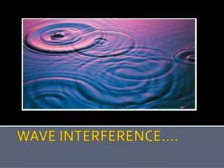
2D Wave Interference
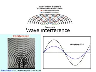
2D Wave Interference. Constructive and Destructive Interference :. When waves overlap, their displacements can CANCEL or ADD UP. Out of phase- ½ Delay. In phase- 0 Delay. Result: Constructive Interference Destructive Interference. 1-D interference.

2D Wave Interference
E N D
Presentation Transcript
Constructive and Destructive Interference: When waves overlap, their displacements can CANCEL or ADD UP. Out of phase- ½ Delay In phase- 0 Delay Result: Constructive Interference Destructive Interference 1-D interference Complete destructive interference occurs when the phase delay between the waves is : ½ , 3/2 , 5/2 , 7/2 ……. Etc. Or The points of destructive interference are called NODES. Or
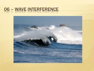
2-D interference 2-D interference simulation Interference of Waves in Two Dimensions : In two dimensions, interfering waves from two sources with the same wavelength produce stationary NODAL LINES: Constructive Interference Destructive Interference Constructive Interference Stationary Nodal Lines Source Separation, d
General Pattern: n=1 ● Nodal lines have a hyperbolic shape but appear STRAIGHT at a distance n=1 n=2 n=2 ● Nodal line number depends on the wavelength and source separation , # d , #
Determining Wavelength: Waves from S1 and S2 arriving at ANY point P on the first nodal line are out of phase by PS1 PS2 Path difference for first nodal line, n=1: For second nodal line, n=2: For third nodal line, n=3: Equation 1: General formula for the nth nodal line: where n=1,2,3…..
II.Angle Dependence of Nodal Lines: At large distances PS1 || PS2 Angles X 90 P Path Difference A A x x n S1 d S1 d S2 S2 Sin n = AS1 d Path Difference=AS1 AS1= dsin n At large distances from the sources, the path difference becomes equal todsin n
We can write this as: |PS1 – PS2|=dsin n Combine with Eqn: 1: We get a second equation with the angle of the nth nodal line: Equation 2: Where n is the nodal line number is the wavelength d is the source separation is the angle of the nodal line Sample Question 3
P III. Cases wheren difficult to measure: In some cases (e.g. light interference), the angles of the nodal lines are not easily measured. x B Centre line C S1 We’ll now identify a way find the angle from distances measured on the interference pattern. nodal pattern L A n n From Triangle BCP we can see: S2 midpoint We will now combine this with equation 2:
Equation 3: Where d- source separation * All distances in metres! - wavelength n = nodal line number L- distance measured from the centre of S1S2 to nodal point P X- the perpendicular distance from the centre line of the pattern to point P Try Sample question 4
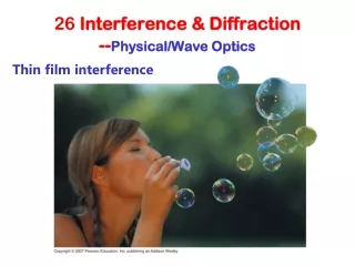
Light Interference: Young’s Double Slit Experiment ● prior to 1802, interference of light was NOT observed Why not? ● incandescent light sources emit incoherent light (random phase) ● very small, so nodal line spacing very small 1802- Young developed the DOUBLE SLIT experiment ● this was the deciding evidence for WAVE model of light
Young’s Experiment: Screen Interference Fringe Pattern Incident sunlight Coherent Spreading wavefronts Bright Bands-constructive interference -maxima Dark Bands-destructive interference -minima x2 Fringe Pattern: x1 Central maximum *From this pattern the easiest measurement is the node to node spacing x n=1 x