Download
1 / 21
210 likes | 302 Views
Explore RF and beam-driven breakdown simulations in hydrogen using Lsp, a versatile PIC code. Compare models and experimental data, analyze breakdown behavior, and investigate the impact of SF6 addition.

E N D
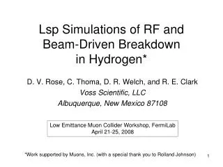
Lsp Simulations of RF and Beam-Driven Breakdown in Hydrogen* D. V. Rose, C. Thoma, D. R. Welch, and R. E. Clark Voss Scientific, LLC Albuquerque, New Mexico 87108 Low Emittance Muon Collider Workshop, FermiLabApril 21-25, 2008 *Work supported by Muons, Inc. (with a special thank you to Rolland Johnson)
Outline: • Lsp simulation code • Particle-in-cell model description • MCC model • Computational representations of the H2 breakdown experiment • 0D model results for H2 • Comparison with RF breakdown experiment • Addition of SF6 • Impact ionization of gas due to H beam • Addition of SF6 • 1D model • Sample RF breakdown calculation • Sample beam-driven and RF breakdown calculation • Discussion • Additional physics (1D electrode emission models, realistic beam emittance, etc…) • Extension to 2D models (computational constraints, scaling) • Summary
Lsp is a general purpose particle-in-cell (PIC) code: • A number of electromagnetic (explicit and implicit), electrostatic, and magnetostatic field solvers are implemented • Kinetic and fluid particle descriptions are available • 1, 2, and 3 physical dimensions; Cartesian, cylindrical, and spherical coordinate systems • Lsp has been used successfully for a number of accelerator and pulsed power applications: • LTD drivers [Sandia National Labs (SNL) LTDR, 6-MV facility] • Heavy ion accelerators [LBNL NDCX I & II] • IVA accelerators [SNL RITS-3, RITS-6, AWE Hydros, Darht] • … and plasma physics applications: • Ion beam sources • Laser-plasma, laser-material interactions • Electron beam diodes for x-ray radiography and pumping excimer lasers • Charged particle beam propagation • EMP applications • Magnetic confinement of plasmas • Wave-wave and wave-particle interactions, instabilities • Moderately and strongly-coupled plasmas
PIC code model: • Charged and neutral plasma species are treated macro-particles, each representing 10xreal particles. (x can be greater than 10!) • EM fields are determined from Maxwell’s equations, solved on a finite grid, with source terms provided by particle charge densities and/or currents mapped onto the grid. • Particle motion governed by fields interpolated from grid to particle positions (typically second-order accurate) [See C. Birdsall and A. Langdon, “Plasma Physics via Computer Simulation” and R. Hockney and J. Eastwood, “Computer Simulation Using Particles”]
Physical Model: the Test Cell (TC) B0 400 MeV H- 5 cm 2.5 cm 3 cm 11.4 cm RF Power Feed:
0D, 1D, and 2D simulation models: Idealized region between electrodes, independent ofspatial gradients and physicalboundaries, but cantreat transient effects (RF field,presence of a beam) 0D: 2.5 cm (cheap) 0D Idealized region spanning space between electrodes, spatial (1D)and temporal gradients and physical boundaries are added.(RF field, beam injection throughelectrode) 1D: (modest sizecalculation) 1D Axi-symmetric approximation(∂/ ∂q = 0), radial gradients are added, RF power can be feed in via a port. 2D 2D: (call in sick)
0D Lsp simulations of RF breakdown in hydrogen: • Lsp model (particle-in-cell Monte Carlo collision model or PIC-MCC) previously benchmarked for RF breakdown in helium [C. Thoma, et al. IEEE Trans. Plasma Sci. 34, 910 (2006)]. • Here, we carry out similar calculations in hydrogen, for direct comparison to experiments [P. Hanlet, et al., EPAC, 2006; M. BastaniNejad, et al., PAC 2007]. • PIC-MCC model uses cross-section data compiled from Boltzmann code calculations and experimental data [D. V. Rose, et al., ICOPS 2007, C. Thoma, et al., Voss Sci. Report VSL-0621 (2006)]. • Here, the model is compared with experimental data for gas pressures less than the electrode breakdown limits.
Lsp sims 0D Lsp calculations in 805 MHz RF field indicate no breakdown at 10 MV/m (blue dot), and breakdown for fields at 25 and 50 MV/m (red dots), consistent with measurements. P. Hanlet, et al., EPAC, 2006
0D simulations of RF breakdown are in agreement with experiments in H2 at 0.002 g/cm3: Seed plasma population has a density of 1010 cm-3, a very small fraction of the initial neutral gas density (6x1020 cm-3). The 25 MV/m simulation shows a very slow growth in electron density (red curve) and the 50 MV simulation (blue curve) shows an extremely rapid breakdown of the gas. At 25 MV/m, breakdown is initially slow but finite (borderline Paschen level). 50 MV/m is well above Paschen level.
Addition of low levels of SF6: • SF6 is a electro-negative gas and the electron attachment channel provides a possible mechanism to reduce the electron density, potentially raising the Paschen curve limit (increasing the breakdown strength of the H2). • Here, we explore 0D calculations of an H2/SF6 mixture (ratio of H2 to SF6 densities = 10-4). • To the 0D simulations we add three species, neutral SF6, SF6-, and SF6+. • The attachment and ionization cross sections for SF6 are composed of experimental and theoretical model data [D. V. Rose, et al., ICOPS 2007, C. Thoma, et al., Voss Sci. Report VSL-0621 (2006)].
0D Calculations with SF6 dopant show rapid reduction in (seed) electron density: For this small level of SF6, electron density prevented from increasing due to attachment of electrons to SF6.
Add streaming proton beam: • Based on Rol’s email (3-27-08), the planned experiment would use 400 MeV proton bunches in an 805 MHz “bucket” • The proton speed incident on the gas cell: b ~0.713 • The bunch “length” is roughly d=bct/2 (I assume a worst-case short bunch of one-half of the sine wave); d~13.3 cm
Estimate proton energy inside gas cell: I used the SRIM dE/dx stopping power tables and fit simple functions for protonstopping in Stainless Steel (vacuum vessel wall material) and Tungsten (electrode material): I assume 1D material layers composed of 5.1 cm of stainless and 2.5 cm of tungsten. A simple calculation shows that the average proton energy entering the gas isroughly 209 MeV (b~0.58).
Beam-impact ionization cross-section estimate: • Impact ionization cross-section for protons on hydrogen gas gives s~4.5x10⁻²³ m2 for 209 MeV protons. • Note: I ignore additional energy loss of the proton beam in the gas as it traverses the AK gap. (for Eb > 5 MeV)
Proton beam density and impact ionization rate: • I assume a cylindrical beam “bunch”, 13.3 cm long, 1-cm in radius, with 1010 protons; the density is then nbeam=2.4x108 cm-3. • For beam impact ionization only, the electron density in the gas evolves as: (I assume ngas = 6x1020 cm-3 as used in the 0D simulations already presented.) So, in 1 ns, you should expect to generate 1012 cm-3 electron density due tobeam impact ionization.
Adding proton impact ionization to the 0D model: • The mean-free path for impact ionization is l=1/(ngass)~4x10-3 cm (for the parameters I used on the previous slide), which is much smaller than the AK gap. • Optionally, we can temporally “switch” on and off the impact ionization algorithm to simulate the ion bunches entering and leaving the gas cell. (not used here) • Adding a more detailed estimate of the ion bunch energy distribution and emittance would be a useful refinement of the 0D calculations.
Impact ionization of H2 gas by the proton beam rapidly drives the breakdown, as expected: 10 MV/m case at 325 psia belowthe Paschen limit 25 MV/m case at 325 psia atthe Paschen limit
0D calculations including proton beam impact ionization indicate that SF6 reduces electron density growth rate slightly: Electron and negative ion SF6densities. Comparison of electron densitieswith and without SF6. • Note: I do not include beam impact ionization of any SF6 species.
1D simulation model: RF fields and proton impact ionization We inject 3 protonbunches into the 1D simulation region through one of theelectrodes. The electron densityincreases significantlydue to proton impactionization of the H2.
Aside: Our group members have done extensive modeling of intense ion beam propagation experiments and theoretical analysis: • 1 MeV proton beam propagation in ~1-10 Torr gases (helium, air, etc., Gamble II generator, Naval Research Laboratory): • P. F. Ottinger, et al., Nucl. Instrum. Meth. Phys. Res. A 464, 321 (2001). • P. F. Ottinger, et al., Phys. Plasmas 7, 346 (2000) • F. C. Young, et al., Phys. Plasmas 1, 1700 (1994). • F. C. Young, et al., Phys. Rev. Lett. 70, 2573 (1993). • J. M. Neri, et al., Phys. Fluids B 5, 176 (1993). • B. V. Oliver, et al., Phys. Plasmas 6, 582 (1999). • Heavy ion beam propagation in <1 Torr gases: • P. K. Roy, et al., Nucl. Instrum. Meth. Phys. Res. A 544, 225 (2005). • S. A. MacLaren, et al., Phys. Plasmas 9, 1712 (2002). • D. V. Rose, et al., Nucl. Instrum. Meth. Phys. Res. A 464, 299 (2001). • D. R. Welch, et al., Phys. Plasmas 9, 2344 (2002). • D. V. Rose, et al., Phys. Plasmas 6, 4094 (1999). • C. L. Olson, et al., Il Nuovo Cimento 106A, 1705 (1993). • B. V. Oliver, et al., Phys. Plasmas 3, 3267 (1996). • GeV proton beam propagation in the atmosphere: • D. V. Rose, et al., Phys. Rev. ST-AB 9, 044403 (2006). • D. V. Rose, et al., Phys. Plasmas 9, 1053 (2002). • Laser-matter interaction and generation of ion beams: • D. R. Welch, et al., Phys. Plasmas 13, 063105 (2006).
Status & Summary: • 0D modeling of RF breakdown in H2 consistent with experimental results. • Addition of proton beam impact ionization rapidly increases electron density in gap: • 0D calculations consistent with simple analytic estimates. • 1D calculations of proton bunches propagating across the electrode gap give density increases consistent with 0D calculations (no channel for rapid electron removal). • SF6 dopant (preliminary results): • 0D calculation including addition of SF6 dopant to H2 (providing electron attachment) showed substantial reduction in electron density near Paschen-curve field-stress levels. • Adding proton beam impact ionization reduced, but did not eliminate, electron density growth (more complete analysis, including H++SF6- should be included). • Next Steps (proposals): • Add electrode physics (e.g., Fowler-Nordheim breakdown) to 1D simulations? • 2D simulations? (Extension to 2D will require revisiting an implicit MCC scattering model rather than the explicit PIC-MCC model used here due to computational constraints.)