Download

1 / 6
110 likes | 347 Views
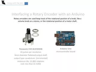
living with the lab. Rotary encoders are used keep track of the rotational position of a knob, like a volume knob on a stereo, or the rotational position of a motor shaft. Interfacing a Rotary Encoder with an Arduino. Arduino Uno microcontroller board. Panasonic EVE-KC2F2024B

E N D
living with the lab Rotary encoders are used keep track of the rotational position of a knob, like a volume knob on a stereo, or the rotational position of a motor shaft. Interfacing a Rotary Encoder with an Arduino Arduino Uno microcontroller board Panasonic EVE-KC2F2024B 24 pulses per revolution 6mm diameter flattened output shaft output type: quadrature (incremental) minimum life: 15,000 rotationscost: less than $1 (USD)
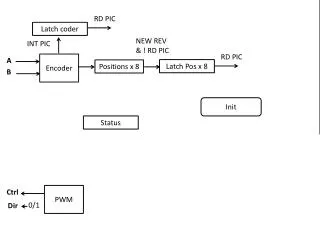
living with the lab Encoder Output and Rotational Direction counterclockwise rotation of knob clockwise rotation of knob B pin A = ON pin A = OFF B A COM A pin B = ON pin B = OFF increment rotational counter When switch A goes OFF and B is ON, then rotation must be clockwise. When switch A goes OFF and B is OFF, then rotation must be counterclockwise. When switch A goes ON and B is OFF, then rotation must be clockwise. When switch A goes ON and B is ON, then rotation must be counterclockwise. decrement rotational counter
living with the lab The Guts of a Mechanical Encoder As the encoder knob is turned, the spring-loaded contacts pass over metal segments that connect to the A, B and COM pins. Electrical continuity occurs when a contact touches metal, but no continuity occurs when a contact touches the black plastic. One of the three contacts is always touching COM. electrical continuity between A and COM no electrical continuity between A and COM spring-loaded electrical contacts A COM B
living with the lab Sensor Wiring (need four 10kΩ resistors and two 0.01F capacitors) 10kΩ 10kΩ 10kΩ 10kΩ this part of the circuit keeps the A, B and COM “switches” from flickering at the beginning or end contact . . . this “debounces” the switches the encoder is the part in the red box
living with the lab A Simple Sketch • This sketch increments the variable “encoderPos” when the encoder knob is turned clockwise and decrements the variable when the knob is turned counterclockwise. • The sketch uses an “interrupt” to avoid missing any changes in the position of the knob. • The Arduino Uno has two interrupts attached to digital pins 2 and 3; we only use pin 2 as an interrupt here. volatile intencoderPos = 0; // the value of a volatile variable can change // in the function called by the interrupt void setup() { pinMode(2, INPUT); // encoder pinA is attached to digital pin2 pinMode(3, INPUT); // encoder pinB is attached to digital pin3 attachInterrupt(0, encoder, CHANGE); // interrupt0 maps to pin2 Serial.begin (9600); } void loop(){ } // main body of the sketch employing the interrupt void encoder() { if(digitalRead(2) == digitalRead(3)) // get state of encoder pins A & B {encoderPos++; } // increment position both are HIGH else {encoderPos--; } // decrement position if both are LOW Serial.println (encoderPos, DEC); // send encoderPos to serial monitor }
living with the lab Example Application This implementation shows a knob mounted to the rotary encoder. This hardware includes two LEDS that come on and off as the encoder passes over the contacts. The hardware can be used with the sketch on the previous slide to demonstrate how the encoder works.