Download
1 / 13
130 likes | 211 Views
Conducted a thermal analysis of a 250GeV beam collimator using a refined mesh, observing temperature rises and stress patterns. Further analyses planned for elevated temperatures.

E N D
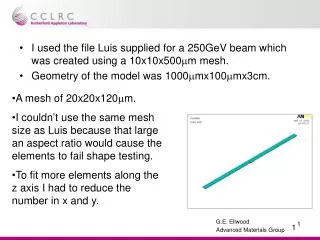
I used the file Luis supplied for a 250GeV beam which was created using a 10x10x500mm mesh. • Geometry of the model was 1000mmx100mmx3cm. • A mesh of 20x20x120mm. • I couldn’t use the same mesh size as Luis because that large an aspect ratio would cause the elements to fail shape testing. • To fit more elements along the z axis I had to reduce the number in x and y.
Due to the amount of elements being used, I decided to conduct only a thermal analysis, initially. • This will enable me to use Luis’ temperature rise figures as a benchmark.
One bunch • The maximum temperature rise after 1 bunch was 233.32°C. Slice along the x-z plane at y=5mm
2 bunches • Max. temp 466.217°C.
Hot Zone in greater detail In future I will refine the mesh in this region and have a courser mesh over the bulk of the volume.
Mesh Sizes • Prior to using the 20x20x120mm mesh (62500 elements), a relatively course mesh of 100x100x500mm was used (500 elements). • This allowed testing of boundary conditions and time step regimes etc. without being computationally expensive. • This led to temperature rises of only ~11°C per bunch as opposed to ~230 °C on the more refined mesh. • Previous meshes used for the entire collimator have been of the order of 6mm.
Coupled Field Analysis • The simulation was repeated using SOLID5 coupled field elements. One bunch, Temperature rise of 221.654 °C. A difference of 10.666 °C compared to using thermal elements.
2nd Bunch • Max temp 448.729 °C, difference of 17.488 °C.
Hottest Node v. time The hottest node was the same in each case. Although the maximum temperature was slightly different, they both displayed a very similar pattern.
Stress at one element v. time • Chose the element which contained the node that reached the highest temperature. • Red crosses indicate time steps • High concentration of crosses at the 0s & 337ns time steps show where the heat loads were applied.
Maximum indicated stress is 735MPa. • I have figures of UTS 950MPa and Yield Stress 880MPa for this alloy. • Unfortunately these are room temperature figures. I haven’t been able to find data for elevated temperatures. • The time between steps could be too large and data points. • Some higher stresses could have been missed. • I will perform further analysis to check the time steps immediately after a beam impact.