Download
1 / 38
430 likes | 737 Views
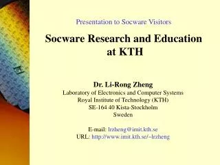
Power Distribution System and Decoupling Allocation Docent Li-Rong Zheng & Prof. Hannu Tenhunen Laboratory of Electronics and Computer Systems Royal Institute of Technology (KTH) SE-164 40 Kista, Sweden (lrzheng@ele.kth.se). Outline. Power Supply Noise and Modeling Techniques

E N D
Power Distribution System and Decoupling Allocation Docent Li-Rong Zheng & Prof. Hannu Tenhunen Laboratory of Electronics and Computer Systems Royal Institute of Technology (KTH) SE-164 40 Kista, Sweden (lrzheng@ele.kth.se)
Outline • Power Supply Noise and Modeling Techniques • Power Regulation and Decoupling Strategies • Power and Ground Plane Design
Technology Scaling of Power Distribution ParametersDevice Per year Chip Per year Wire Pitch x 0.87 Chip Edge y 1.06 IR/V 1/x 1.15 y2/x3 1.71 (L/V)dI/dt (package) 1/x 1.15 y2/x3 1.71 (L/V)dI/dt (on-chip) 1/x2 1.32 y2/x4 1.96 Why Power Distribution? -- An ITRS’ View Chip power for future ULSI Power Loss: DC voltage drop: DV=RI Switching noise: DV=L dI/dt The future Challenge: how to delivery 100A current at ~1V from board to chip ?
Power Supply Noise VDD (off-chip) Lpin iL(t) Vdd (on-chip) Vin CL Lpin Vdd Simultaneous Switching Noise: Power bounce Gnd DC loss: Ground bounce
The Packaging Parasitics L-C Tank Circuit
System level power delivery network High-Frequency on-chip global and semi-global lines Impedance (ohms) 0.025 0.020 0.015 0.010 0.005 0.000 Zs High-Frequency Chip on SCM/MCM Mid-Frequency SCM/MCM on Board Target Impedance Low-Frequency Power Regulator 100 101 102 103 104 105 106 107 108 109 1010 Frequency (Hz) Task of Power Distribution Design: Zs < Ztarget (in Frequency Domain)
Target Impedance: Trends in This Decade • Target impedance is falling ~1.6X, every 3 years
Iin , Vin ut Iut,Vut IL Load-off Load-off Impedance (log) Impedance (log) Load-on Load-on Frequency log(Hz) Frequency log(Hz) Transfer-impedance Self-impedance Definitions of Impedance: Very Confused So Far! Self-impedance: apply 1 amp current Iinat input only, measure the voltage at input. (two cases: load-on or load-off) Transfer-impedance: apply 1 amp current Iinat input only, measure voltage at load (ut). (two cases: load-on or load-off)
Power Distribution System Design Chip power supply noise is very much dependent on packaging. Chip-packaging co-design is needed for a good PDS design.
Vss Contact vias Vdd Active devices On-Chip Power Distribution Resistance: (DC resistance and AC resistance due to Skin effect) Capacitance: C= Cwire+Csymbiotic+Cdecoupling Inductance (accurate data will need 3D field solvers): Bonding wire ~10nH/cm, TAB ~ 8nH/cm, Flip-chip sold-bump~7nH/cm Typical value: bonding wire ~1-2.5nH, TAB ~2-6.3nH, Flip-chip <0.1nH On-chip inductance: if Rwire >> jwLwire, on-chip inductance is negligible
Logic Logic Logic Logic Cell Cell Cell Cell External supply > 0.35mm, tr (tf) >350ps < 0.18mm, tr (tf) <100ps On-chip Power Distribution: Circuit Model
Power Supply Decoupling Provided a small current-loop for fast switching. Provided the AC current needed by the device.
I Iavg t On-Chip Decoupling Requirements Hand Calculation (pessimistic) L Cd Dt: switching time, DV: allowed ripple voltage tck: clock period, Iavg: time averaged current. or Typically ki=0.25~0.5 (ki=1 for delta function, =0.25 for triangle wave, =0 for a DC current) Industrial Example IBM Power4: ~300nF of decoupling capacitors 4172 power and ground pins, 2208 signal pins (C4) IBM Z900: ~250nF on-chip decoupling capacitors Compaq EV6: ~320nF decoupling, occupy 15-20% chip area !
Cwire Vss Vdd n-well Cgate Cwell p-sub On-chip Decoupling Capacitors A capacitor chip is bonded to an DEC 21264 processor chip to provide power conditioning “Near-chip” Vdd IBM S390 MCM Module Vss Off-chip (on-module)
on on 0 1 0 on Symbiotic Bypass Capacitance Symbiotic Bypass Capacitor Example: in 0.18um CMOS process, Cox is about 10fF/um2, Cld=50fF/gate. For a 100K gate module with 4% gates switching simultaneously, the remaining gates will connect about half of their output load across the power supply. This will give a symbiotic bypass capacitance of about 2.4nF.
Vdd pins Vss pins Low Inductance Packaging: Area Array Power Pin Connection Peripheral edge power pin distribution Area array power pin distribution • Area Array Connection Power/Ground Pin Distribution for External Supply • Self-Decoupling between Vdd and Gnd Inductance < 0.1nH/pin
Lvdd Id P G P G S S S M G P G P S S S Lvss P G P G Is S S S G P G P Low Inductance Packaging: Pin Assignment Area Array (C4) If Lvdd=Lvss=Lp, Is=Id , Equivalent inductance (loop): Total Inductance: Increase mutual coupling, increase # of power/ground pins, balance Id and Is locally
Ground Signal Power On-Chip Power Distribution Schemes Double Layer Mesh (with high speed signal distribution) Solid Planes (large decap, many vias) Single Layer Grid Distributed at top-most metal layers (thicker, low R metals)
Off-Chip Decoupling Capacitor Allocation Plane inductance (W: width between two pwr pins; H: separation between power and ground planes, all in cm).
Power distribution principles • Use low impedance ground connections between ICs • The impedance between power pins on any two ICs should be as low as the impedance between ground pins • There must be a low impedance bath between ground and power • This path must be LOW impedance on all frequencies of interest in order to handle all fast charging/discharging on chip • Inductances are the limiting factor! • These will be compensated with global and local capacitors for supplying momentary charge to chips
Poles and Zeros of a Board populated with Decoupling Capacitor
Realistic Impedance Profile of a Board Populated with Decoupling Capacitor
Modeling of a PCB Power Plane Transmission lines