Download

1 / 66
700 likes | 1.01k Views
Coherent Lightwave Systems. CONTENTS. Principles of coherent and non-coherent detection : heterodyne and homodyne detection; Modulation formats: ASK,PSK,FSK,PPM,DPSK;. CONTENTS. Demodulation schemes : synchronous and asynchronous demodulation; Bit error rate performance analysis;.

E N D
CONTENTS • Principles of coherent and non-coherent detection : • heterodyne and • homodyne detection; • Modulation formats: • ASK,PSK,FSK,PPM,DPSK;
CONTENTS • Demodulation schemes : • synchronous and • asynchronous demodulation; • Bit error rate performance analysis;
CONTENTS • Performance degradation due to: • laser phase noise, • group velocity dispersion, • self phase modulation, • polarization mode dispersion, • relative intensity noise, • effect of timing jitter;
CONTENTS • System design considerations: • power budget, • rise time budget, • power penalty.
Modulation Modulation process: Switching or keying the amplitude, frequency, or phase of the carrier in accordance with the information binary bits. The modulation can be either: • Direct modulation • Light is directly modulated inside a light source • External modulation • Using external modulator
IM-DD system • Applied in the first generation (1970’s) intensity modulation direct • detection is still the most used for optical communications • Information is carried only by the intensity • not frequency or phase Optical detection • The received signal is applied directly to photodetector • Photo-detection of light represents the key operation in the optical receiver. • Converting the collected field onto a current or voltage.
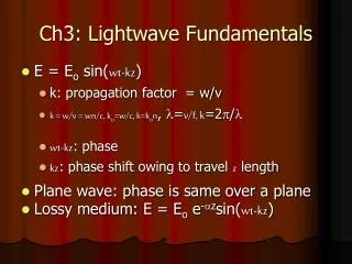
Light is described as a stream of photons (quanta) • The theory of quantum states that the energy of a photon is proportional to the frequency of light Where the Plank constant h = 6.6261 10-34 W s2
For modulated optical signal with power P(t), the instantaneous photon intensity (photon flux) varies with time: • Let P the optical power of a light beam, then the number of photons per second is: photons/s
Where is the quantum efficiency of the device and E is the energy received in a time interval T. • For a PIN-diode photodetector, the average number of electron-hole pairs generated in a time interval of T is given by
The ideal receiver • Consider an ideal OOK transmission system over an ideal channel • The transmitter sends light for a one • No light for a zero • The receiver counts N, the number of photons it receives in a bit interval of T seconds, and zero otherwise
If a zero is transmitted, then there is a zero probability of receiving zero photons. • If a one is transmitted, then the photons arrive according to a Poisson process with mean m • For a ONE, the probability of receiving N photons in T seconds is given by by the Poisson distribution.
Quantum limit • It is possible that no photons arrive when a ONE is transmitted. This leads to a probability of error or a Bit-error-ratio (BER), of • This leads to an important lower bound on the BER called the quantum limit • It indicates a minimum signal power required by an OOK receiver to achieve a given BER
Example: • Letting BER= 10-9 gives m = 20.03. • Hence, to achieve a BER of 10-9, the pulse must have an optical energy corresponding to an average of 20 photons. • On average, half the signal intervals contain optical pulses, and the average number per transmitted bit is: • This quantity of of 10 photons/bit is called the quantum limit for optical detection. • It represents a lower limit on the received power necessary in a direct detection.
Practical receiver Receiver configuration IM-DD system can only be used for OOK modulation format
Shot noise Shot noise (from O-E counting process in PIN): is the average photocurrent is a stationary random process with Poisson statistics is(t) can be approximated by the Gaussian statistics with its variance given by:
Thermal noise Including thermal noise (from carrier moving in any conductor): current fluctuation induced by thermal noise iT(t) can be modeled as a stationary Gaussian random process with its variance given by: Its spectral density (“white noise”) is given by:. Boltzmann constant, the absolute temperature, and the load resistor
Total receiver noise Considering the dark current from PIN and the enhancement to thermal noise from the components other than the load resistor in the linear channel, the total noise variance is: the PIN dark current and the amplifier noise figure
the APD gain and the APD excess noise factor is the ionization-coefficient ratio. Receiver signal to noise ratio PIN receiver: APD receiver: Where
BER Analysis for IM/Direct Detection The bit error rate can be computed as: where • Pr(0/1) is the probability that a "0" is received • when a "1" is transmitted. • Pr(1/0) is the probability that a "1" is received • when a "0" is transmitted • The values of Pr(0/1) and Pr(1/0) depends on the statistical • nature of the output signal in the presence of noise.
For a binary symmetric channel, p(0)=p(1)=1/2 which • indicates equal probability of occurrence for a "1" and a "0" bit. The output signal current is given by Where in is the noise current due to shot and thermal noise. The probability density function of in is given by • where imean=0 is the mean value of in.
Bit Error Rate The bit error rate can be computed as:
Since in is Gaussian with zero mean and variance n2 , • the probability density function (pdf) of the receiver • output corresponding to bit "1" and bit "0" are also • Gaussian with mean I1 and I0 respectively and given by where 12 and 02 are the noise variances corresponding to bit "1" and bit "0" respectively.
Minimum BER occurs when Pr(0/1)=Pr(1/0) which corresponds to an optimum value of the threshold current ith and can be determined as The optimum threshold is then given by Under the assumption that the noise current is same for bit "0" and bit "1", 1=0, then the optimum threshold is given by The above optimum threshold is applicable in absence of laser phase noise. In the presence of laser phase noise, the optimum threshold is to be determined numerically because 1 does not equal 0.
The value of the parameter Q at the receiver output under optimum threshold condition is expressed as and the corresponding BER for optimum threshold is given by
The output SNR (= signal power to noise power ratio) for a PIN-receiver is given by where Be=Br/2. In terms of number of photons per bit N, the BER can be expressed as where Where we assumed that I0=0 and 0= 0 which is valid when the receiver is dominated by shot noise.
hence and
Beam Combiner Electrical Signal Output Optical Signal Input Photo- Electronic Detector Circuits Local Optical Oscillator CoherentDetection Coherent detection receiver adds light to the received signal as part of the detection process Coherent receiver model
Detection Schemes • Homodyne detection • The optical signal is demodulated directly to the baseband. • It requires a local oscillator whose frequency match the carrier signal and whose phase is locked to the incoming signal ( c= LO). • Information can be transmitted through amplitude, phase, or frequency modulation • Heterodyne detection • Neither optical phase locking nor frequency matching is of the local oscillator is required ( c LO). • Information can be transmitted through amplitude, phase, or frequency modulation
Demodulation schemes in coherent detection • There are two basic types of demodulation in coherent detection of optical signals : (a) Synchronous demodulation (is essential for homodyne detection) (b) Asynchronous demodulation
Optical Detection Modulated signal: Local oscillator signal: The output power of the photodetector where
Homodyne Detection The detector current: Heterodyne Detection The detector current:
Beam Combiner Optical Signal Input Photo- Detector BPF Delay LPF Baseband Signal Output Local Optical Oscillator Carrier Recovery Heterodyne Synchronous Coherent Receiver • In which the IF modulated signal is mixed with an IF carrier recovered from the IF signal. At the output of the mixer the baseband signal is received which is filtered by a low pass filter and fed to the decision circuit.
Heterodyne detection needs neither frequency matching nor phase locking. • The detected electrical signal is carried by the intermediate frequency and must be demodulated again to the baseband. • This demodulation scheme can be used for ASK, FSK or PSK modulation formats.
Heterodyne Synchronous ASK The detector current: its mean square is : The thermal noise and shot noise variances : where
If the bit rate is Br=1/T, then average signal power Let Be=Br/2, then SNR can be expressed The corresponding BER for heterodyne ASK receiver is
Receiver sensitivity Receiver sensitivity can be defined as the minimum required received optical power to attain a BER of 10-9 which corresponds to Q=6 or when SNR=144 or 21.6 dB. Average received power Pr can be obtained as For an ideal photodetector =1 and the number of photons per bit required for BER=10-9 is 72 for ASK heterodyne.
Heterodyne Synchronous ASK in the presence of noise The current after photo-detection (the output of the photodiode is passed through a BPF centered at the IF frequency and the filter out put can be written as:) The noise at the output of the filter can be expressed in terms of its in-phase and quadrature components as : where (Gaussian random variables with zero mean) The variance are given by:
With noise included after BPF: It shows that only the in-phase noise component affects the performance of synchronous heterodyne receivers. After synchronous (coherent) demodulation and LPF
Or where The analysis is analogous to that for direct detection receiver and the BER is given by where Where we assumed that I0=0 and 0= 1 which is valid when the receiver is dominated by shot noise at higher values of PLO.
Homodyne Synchronous ASK The detector current: its mean square is : The thermal noise and shot noise variances : where
IF- Signal to noise ratio (IF-SNR) : Or where R=e/h
If the bit rate is Br=1/T, then average signal power Let Be=Br/2, then SNR can be expressed The corresponding BER for homodyne ASK receiver is For an ideal photodetector =1 and the number of photons per bit required for BER=10-9 is 36 for Homodyne Syn. ASK.
Homodyne Syn. ASK Versus Heterodyne Syn. ASK ASK homodyne receiver requires 3 dB less power and is therefore 3-dB more sensitive than ASK heterodyne receiver. Heterodyne Detection versus IM/DD Sensitivity Improvement of 10 dB to 20 dB Frequency selectivity IF domain signal processing provides better performance Heterodyne Detection Receiver is more sensitive to the phase noise of lasers Additional signal power is required for the same reliability of operation which is called power penalty