Download
1 / 43
430 likes | 552 Views
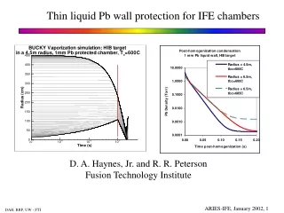
Dry-Wall Target Chambers for Direct-Drive Laser Fusion. Gerald L. Kulcinski, Robert R. Peterson and Donald A. Haynes presenting for the staff of the Fusion Technology Institute University of Wisconsin-Madison. Laser IFE Workshop February 6-7, 2001 Naval Research Laboratory.

E N D
Dry-Wall Target Chambers for Direct-Drive Laser Fusion Gerald L. Kulcinski, Robert R. Peterson and Donald A. Haynes presenting for the staff of the Fusion Technology Institute University of Wisconsin-Madison Laser IFE Workshop February 6-7, 2001 Naval Research Laboratory
Program Plan for the Design of Dry-Wall Target Chambers for Direct Drive Laser Fusion-U. of Wisconsin (WBS 3.1-3) FY 01 Deliverables……… 1. Calculate threat spectra to first wall and assess methods to eliminate wall ablation. FY01 Funding $500 k Relevance of Deliverables NIF-Wall survival (1,3), Safety (3) DP/NNSA-Reaction products, opacity modeling (1) Energy-IFE Power Plants (1,2,3,4) Overall Objective…………..Integrated direct drive fusion chamber concept 2. Identify injection conditions that will allow several direct drive targets to survive to thermal environment inside the chambers. 3. Design blanket and shielding to protect critical components. 4. Incorporate innovative concepts into previous designs.
Elements of UW FY 01-02 Research on Dry Wall Target Chambers for Direct Drive Laser Fusion Previous Work Threat Spectra New Chamber Blanket Design 50 % 30 % Shielding of Critical Components FW Response Target Heating Incorporate into Improved Chamber Design 20 %
F M A M J J A S O N D J Chronology of UW Work on Dry Wall Laser Chambers Threat Spectra and Target Heating Blanket/FW Design and Shielding Incorporate into Improved Chamber Design
Key Personnel for FY01-02 Work on Laser Fusion Chambers-University of Wisconsin Threat Spectra and Target Heating Robert Peterson Donald Haynes Igor Golovkin Greg Moses Elsayed Mogahed Igor Sviatoslavsky Paul Wilson John Santarius Gerald Kulcinski Chamber Design and Shielding Mohamed Sawan Laila El-Guebaly Doug Henderson Hesham Khater Elsayed Mogahed Igor Sviatoslavsky Gerald Kulcinski Improved Chamber Design Igor Sviatoslavsky Mohamed Sawan Robert Peterson Gerald Kulcinski
Target Output and First Wall Calculations for Laser Fusion Chambers Robert R. Peterson, Donald A. Haynes and Igor E. Golovkin University of Wisconsin-Madison Fusion Technology Institute US-Japan Workshop on Laser Fusion January 25-27, 2001 Lawrence Livermore National Laboratory
Objective of Present Study • To understand if the recent NRL direct drive target design can survive in a SOMBRERO-type dry wall chamber (no vaporization of C-C composite) • To investigate the degree to which the Xe fill gas could be reduced to lower the aerodynamic frictional heating of direct drive targets. • Apply latest analysis methods and explore the possibility of innovative injection techniques in dry wall chambers
First Wall Erosion and Target Heating During Injection are Competing Concerns in Direct-Drive Laser Fusion Dry-Wall Target Chambers
Chamber Physics Critical Issues Involve Target Output, Gas Behavior and First Wall Response Target Output Gas Behavior Wall Response Design, Fabrication, Output Simulations, (Output Experiments) X-rays, Ion Debris, Neutrons Gas Opacities, Radiation Transport, Rad-Hydro Simulations Thermal Radiation, Shock Wall Properties, Neutron Damage, Near-Vapor Behavior, Thermal Stresses UW uses the BUCKY 1-D Radiation-Hydrodynamics Code to Simulate Target, Gas Behavior and Wall Response.
BUCKY, a Flexible 1-D Lagrangian Radiation-Hydrodynamics Code; Useful in Predicting Target Output and Target Chamber Dynamics • 1-D Lagrangian MHD (spherical, cylindrical or slab). • Thermal conduction with diffusion. • Applied electrical current with magnetic field and pressure calculation. • Equilibrium electrical conductivities • Radiation transport with multi-group flux-limited diffusion, method of short characteristics, and variable Eddington. • Non-LTE CRE line transport. • Opacities and equations of state from EOSOPA or SESAME.
BUCKY, a Flexible 1-D Lagrangian Radiation-Hydrodynamics Code; Useful in Predicting Target Output and Target Chamber Dynamics • Thermonuclear burn (DT,DD,DHe3) with in-flight reactions. • Fusion product transport; time-dependent charged particle tracking, neutron energy deposition. • Applied energy sources: time and energy dependent ions, electrons, x-rays and lasers (normal incidence only). • Moderate energy density physics: melting, vaporization, and thermal conduction in solids and liquids. • Benchmarking: x-ray burn-through and shock experiments on Nova and Omega, x-ray vaporization, RHEPP melting and vaporization, PBFA-II K emission, … • Platforms: UNIX, PC, MAC
Direct-Drive Targets Under Consideration Have Different Output The energy partition and spectra for SOMBRERO were supplied by DOE and need to be calculated. Direct-drive Laser Targets SOMBRERO (1990) NRL (1999) NRL (1999) Standard Direct-Drive Radiation Tailored-Wetted Foam Wetted Foam 1 CH + 300 Å Au 1 CH CH 3.0 mm Foam + DT 1.62 mm 1.95 mm DT Fuel Foam + DT 2.7 mm DT Fuel 0.265g/cc DT Fuel 0.265g/cc 2.5 mm 1.69 mm DT Vapor 0.25 g/cc DT Vapor 1.44 mm 0.25 g/cc 1.50 mm DT Vapor 1.22 mm Laser Energy: 1.3 MJ Laser Type: KrF Gain: 127 Yield: 165 MJ Laser Energy: 4 MJ Laser Type: KrF Gain: 100 Yield: 400 MJ Laser Energy: 1.6 MJ Laser Type: KrF Gain: 108 Yield: 173 MJ Debris Ions 94 keV D - 5.81 MJ 141 keV T - 8.72 MJ 138 keV H - 9.24 MJ 188 keV He - 4.49 MJ 1600 keV C - 55.24 MJ Total - 83.24 MJ per shot • Spectra: • Calculated with BUCKY • Calculated by NRL • Calculated with Lasnex • Spectra: • Not Yet Calculated
Laser Quickly Burns though 300 Ǻ Au and Radiatively Pre-Heats the Ablator Laser Au CH DT-wetted Foam • Close-up of laser burning through thin gold and plastic shells of NRL target • Gold and plastic are hot and rapidly rarifying, probably not in local thermodynamic equilibrium. • Gold is expanding at 75 km/s from laser blow-off.
Implosion, Burn and Explosion of NRL Radiation Smoothed Direct-Drive Laser Fusion Target • 22% of DT ice is burned; NRL and LLNL get about 32 %, though peak R (LLNL) and bang time (NRL) do agree. • Very little DT in wetted foam is burned. • This calculation yielded 115 MJ; another, 200 MJ • Other yields would be achieved with further tuning. • Target expands at a few time 108 cm/s and radiates.
Ion Spectrum for NRL Radiation Pre-Heated Target Depends on Yield DT Ice DT Ice DT Gas DT Gas Wetted Foam Wetted Foam Plastic Plastic Au Au SOMBRERO SOMBRERO • The particle energy of each species in each zone is then calculated as mv2/2 on the final time step of the BUCKY run. This time is late enough that the ion energies are unchanging. The numbers of ions of each species in each zone are plotted against ion energy. • The spectra from direct fusion product D, T, H, He3, and He4 are calculated by BUCKY but they don’t make it out of the target. • The ion spectra is more energetic for 200 MJ yield Ion Spectrum for 115 MJ Yield NRL Target Ion Spectrum for 200 MJ Yield NRL Target
Ion Spectrum Experiments on Z are in Progress to Validate Target Output Calculations Ablator Material CR39 film measures ion energy through damage track lengths. Open collimator LOS 1/2 8” from Z Z X-rays CR39 detector Z-pinch x-ray source Pin Hole Camera 10 degrees tilt to center. 9” from center of camera hole plate to blast shield. Damage by ions L I D Concept SHOT # 60306/26/00 16:13 Ion track analysis and supporting BUCKY simulations are in progress.
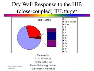
X-ray Spectra from Targets is Changed by High Z Components and Yield • X-ray spectra are converted to sums of 3 black-body spectra. • Time-dependant spectra are in Gaussian pulses with 1 ns half-widths and are used in chamber simulations. • Time-integrated fluences are shown for 115 MJ and 200 MJ NRL and 400 MJ SOMBRERO. • The presence of Au in the NRL targets adds emission in spectral region above a few keV. • At higher yield the Au is more important. NRL 116 MJ NRL 200 MJ SOMBRERO 400 MJ
Some debris ions are deposited in chamber gas, which re-radiates the energy in the form of soft x-rays Some debris ions are absorbed directly in the wall. The x-rays directly released by the target are, for Xe at the pressures contemplated for the DD target, almost all absorbed by the wall. The threat spectrum can be thought of as arising from three contributions: fast x-rays, unstopped ions, and re-radiated x-rays The wall (or armor) reacts to these insults in a manner largely determined by it’s thermal conductivity and stopping power.
For example, the first wall does not vaporize for the SOMBRERO target in a 6.5m radius chamber filled with 0.1 torr Xe and a wall equilibrium temperature of 1450C. • The separation in time of the insults from the prompt x-ray, the ions, and the re-radiated x-rays is crucial to the survival of the wall. • The Xe serves to absorb the vast majority of the ion energy and almost half of the prompt x-rays and slowly re-radiates the absorbed energy at a rate determined by the Plank emission opacity of the Xe.
For the current calculations, IONMIX has been used to generate Non-LTE Xe opacity tables • Xe gas at or below 0.5 Torr in Density is not in LTE. • Non LTE (IONMIX) ionization is substantially below the LTE (Saha) ionization. • The Xe opacity can differ substantially between LTE (EOSOPC) and Non-LTE (IONMIX). • IONMIX opacities are used in this study.
A scan of Xe density holding the first wall equilibrium temperature fixed at 1450C was performed to examine the onset of vaporization. • For the SOMBRERO target in a 6.5m graphite chamber, the prompt x-rays are the major threat. • Even at 0.05 Torr Xe, 78MJ of the 83MJ of ion energy is absorbed by the gas, slowly re-radiated to contribute to the second peak in temperature. • The sublimation threshold occurs when the prompt x-rays loading is above 1.88 J/cm2 for x-rays with the SOMBRERO spectrum, for this equilibrium wall temperature.
The SOMBRERO and NRL targets differ significantly in yield, partitioning, and spectra. These differences lead to very different target chamber dynamics. • Even if the NRL spectra are scaled up by the ratio of the total yields (400/165), it poses considerably less threat to the target chamber. • It has fewer of the dangerous, prompt x-rays and a different ion spectrum. • For instance, the first wall survives at conditions where the SOMBRERO target vaporizes 6.7g of wall material per shot. (This assumes that the energy is increased by increasing the flux, and not the shape, of the spectra..)
Detail: Carbon and deuterium deposition and X-ray spectra for SOMBRERO and Scaled NRL Targets in 6.5m Radius C Chamber Xe density is 50 mtorr and wall temperature is 1450 ° C. The spectra differ primarily due to the Au and knock-ons in the NRL spectrum and the 55MJ of 1.6MeV C ions in the SOMBRERO spectrum. The NRL knock-ons heat the 1st mm of the wall volumetrically.
A C-C Target Chamber Can Survive, with Proper Gas Protection and Wall Temperature • A series of BUCKY calculations have been performed of the response of a 6.5 m radius graphite wall to the explosions of SOMBRERO and NRL targets. Time-of-flight dispersion of debris ions is important, especially for low gas density. • The gas density and equilibrium wall temperature have been varied to find the highest wall temperature that avoids vaporization at a given gas density. • Vaporization is defined as more than one mono-layer of mass loss from the surface per shot. • The use of Xe gas to absorb and re-emit target energy increases the allowable wall temperature substantially.
First Wall Erosion and Target Heating During Injection are Competing Concerns in Direct-Drive Laser Fusion Dry-Wall Target Chambers
Target Injection for Laser Fusion Chambers G.L. Kulcinski, E. A. Mogahed, and I. N. Sviatoslavsky University of Wisconsin-Madison Fusion Technology Institute US-Japan Workshop on Laser Fusion January 25-27, 2001 Lawrence Livermore National Laboratory
Assumptions For NRL Target Heating Calculations • Injection velocity = 400 m/s • Target spectral reflectivity = 99% • Transport distance in chamber = 2 m (tube) • Thermal diffusivity of CH @ 18 K = 0.009 cm2/s • DT at DT/CH interface < 1.5 K • Tumbling target (symmetric heat transfer)
The Heat Flux Absorbed in the Outer Surface of the Target Depends on the FW Temperature and the Target Emissivity 17
The Heat Flux Due to Aerodynamic Friction on the Target Outer Shell is Strongly Dependant on the Chamber Gas Density and the Velocity of the Target. Frictional Heat Flux for a 6 mm Diameter Target Frictional Heat Flux for a 4 mm Diameter Target
Monte-Carlo Frictional Heating Calculation Monte-Carlo Frictional Heating Calculation Xe density = 3.2 1014 cm-3 (0.009 Torr) T = 1500 K mfp = 2.2 mm Sound speed = 364 m/s Target diameter = 4 mm Injection speed = 400 m/s Xe density = 3.2 1014 cm-3 (0.009 Torr) T = 1500 K mfp = 2.2 mm Sound speed = 364 m/s Target diameter = 4 mm Injection speed = 400 m/s .0006 0012 .0006 0012 -.0012 -.0006 0 -.0012 -.0006 0 Axial Distance from Target Center (m) Axial Distance from Target Center (m) Since the collisional mean-free-path is the same order as the target size, a detailed calculation is needed. UW has started the use of a 2-D Monte-Carlo Hydrodynamics Code from Sandia to Model Frictional Target Heating This calculation was performed with the Icarus code by Tim Bartel of SNL.
Max Ave The Heat Flux Due to Aerodynamic Friction on the Target Outer Shell is Strongly Dependant on the Chamber Gas Density and the Velocity of the Target. Frictional Heat Flux for a 6 mm Diameter Target Frictional Heat Flux for a 4 mm Diameter Target
The Target Injection Tube Protects the Target from Thermal Damage During Injection Pressure Profile in Target Injection Tube as a Function of Distance from Chamber Center 10 Chamber Target Injection Tube Center 1 .1 Gas Pressure Profile in Tube (torr) .01 Molecular flow regime Throughput 8e-5 torr l/s.cm2 Pumping speed 34 cm3/s .001 CROSS-SECTION OF SOMBRERO CHAMBER 0 2 4 6 8 Distance Along Injection Tube (m) • A target injection tube extends from the top of the chamber to within 2 meters of the chamber center. • It consists of a tungsten core which is He gas cooled in a closed cycle cooling system. • The tungsten core is surrounded by a carbon double tube assembly cooled by Xe gas, extending 0.5m beyond the tungsten core. • The Xe gas after cooling the carbon tube enters the chamber replenishing the chamber buffer gas. • The tungsten core is stationary, but, the carbon tube is slowly moved forward at the rate at which the carbon evaporates. • The target is shielded from high temperature radiation from the first wall, and by tube differential pumping avoids frictional heating with the buffer gas along most of its trajectory.
TARGET INJECTION TUBE DETAILS PARAMETERS OF TARGET INJECTION TUBE Material ID (cm) OD (cm) t (cm) Inner W tube W 1.0 1.6 0.3 Outer W tube W 2.4 3.0 0.3 Coolant Flow area He 1.6 2.4 0.4 Inner Graphite tube C 3.0 3.4 0.2 Outer Graphite tube C 4.4 5.0 0.3 Coolant Flow area Xe 3.4 4.4 0.5 THERMAL HYDRAULIC PARAMETERS OF TARGET INJECTION TUBE W tube coolant He gas Length of W tube(m) 4.0 Nuclear heating in W tube (Kw) 86.0 He gas pressure (atm) 80.0 Inlet temperature (K) 77 Outlet temperature (K) 300 He gas velocity (m/s) 21 Average temperature of inner W wall (K) 250 Graphite tube coolant Xe Length of tube (m) 4.5 Nuclear heating in graphite tube (Kw) 48.0 Radiant heating in graphite tube (Kw) 30.0 Xe gas pressure (atm) 10 Inlet temperature (K) 300 Outlet temperature (K) 1174 Xe gas velocity (m/s) 81 Average temperature of inner graphite tube (K) 1000
It is Difficult to Find an Operational Regime for the NRL Target in a Dry-Wall Chamber (Assuming 1.5 K Fuel Temperature Rise) Chamber radius of 6.5 m Tumbling target 160 MJ 400 MJ Region Excluded due to Radiation Damage Accumulation
Survivability of Targets and C-C First Walls in SOMBRERO Dry Wall Chamber with No Fill Gas No (evaporation, unless TFW < RT) Yes (TFW<2,100 °C) Yes (if TFW<1,600 °C) Yes (if TFW<1,500 °C)
Survivability of Targets and C-C First Walls in SOMBRERO Dry Wall Chamber with 0.1 Torr Xe Fill Gas Yes (TFW<1,600°C) Yes (if TFW<2,100 °C) No Solution (TFW<< RT)) No (frictional heating, TFW << RT)
Survivability of Targets and C-C First Walls in SOMBRERO Dry Wall Chamber with 0.01 Torr Xe Fill Gas No (evaporation, unless TFW < RT) Yes (TFW<2,100 °C) Yes (if TFW<1,600 °C) Yes (if TFW<1,600 °C)
Parametric Studies for Laser Chamber Analysis, Feb. to Oct. 2001 • Targets NRL-ref, SOMBRERO, NRL-400 • Temp Rise in DT, K 1.5, 5, 10 • Target Reflectivity 0.2, 0.9, 0.99 • Injection Velocity, m/s 200, 400 • Distance Target Exposed, m 2, 6.5, 8 • FW Material C-C, SiC, W • Cavity Gas Xe, Kr • Gas Pressure, Torr 0, 0.01, 0.1
Laser Dry-Wall Chamber Program Plan Establish Operating Windows (sufficient for 1,000 MWe) Incorporate New Target Designs Target Spectra Exp. & Survival Experiments on Target Heating New Target Survival Criteria Power Plant Point Design Imbed Two Chamber Designs into Sombrero Reference Full Analysis of Improved Dry Wall Ref. Design Scope New Ref Design Experimental Validation of Materials Experimental Results On Radiation Damage of Chamber Materials Establish operational parameters for FW/Blk Begin First Material Radiation Damage Studies Test Thermal Life & Prepare Irr. Capsules Chamber Clearing Reestablish Baseline Target Injection Parameters Define Cavity Gas Dynamics Test time to damp cavity gas Experiment on Target Injection in Hot Turbulent Dilute Gas Safety and Environment Establish Allowable Inventory & Release Experiments on T2 & Radioisotope Release Design Basis Accident Analysis FY 2001 | FY 2002 | FY 2003 | FY 2004 | FY 2005 |