Injector Drive Laser Update
The design of the S20 Drive Laser facility is progressing, with contractor bids due on April 14th. A vendor for the Drive Laser has been selected, and contract procurement is underway. Key designs for transport tubes and systems are nearing completion, with radiation shielding approval pending. R&D efforts have commenced, including collaborations with LLNL and ANL on UV conversion and temporal shaping. The procurement process is highlighted, showcasing vendor evaluations and selections, with attention to resolving potential issues and risks.

Injector Drive Laser Update
E N D
Presentation Transcript
Injector Drive Laser Update • Project Status • Drive Laser Procurement • R&D • Launch System Design Facilities Advisory Committee Meeting April 7, 2005
Project Status • Design of the S20 drive laser facility is underway. Bids are due from general contractors on April 14th • The vendor for the Drive Laser is selected. Purchasing is working on the award of the contract. • Basic design of the transport tubes done; drawings submitted for the quote. Shielding should be approved by radiation physics. • Design of the Launch and Conditioning System is near completion • R&D effort is defined and started. BCR is approved • LCLS performs shaping & UV conversion R&D with other labs (LLNL, ANL) • BNL temporal shaping work with Dazzler completed
Drive Laser Procurement Process Drive Laser Technical Review July 21, 2004 Evaluate RFI & Technical Review Responses Write Request for Proposal (RFP) Write Request for Information (RFI) Write & Approve Advance Procurement Plan (APP) Submit RFP to Vendors Evaluation & Technical Committees Review the Proposals Evaluation Committee Ranks the Proposals Evaluation Committee Selects Vendor SLAC Awards Contract Site Visit
Drive Laser Procurement Responding to the RFP 5 Companies submitted the proposals Toptica Photonics
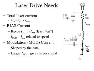
Drive Laser Proposals • Only Thales signed to meet all the specs • Thales sold high energy IR system with the Dazzler • KM Labs and Femtolasers manufacture oscillators • Thales and Coherent manufacture DPSS pump lasers • KM labs proposed 1KHz system • Cryo cooling of the final amplifier (Coherent, KM labs, Amplitude) • Nobody has experience with UV temporal shaping and can guarantee meeting UV temporal shaping specs • Amplitude and KM Labs proposed R&D plan for UV temporal shaping • Temporal shaping. KM Labs proposed passive optical filtering with LCD modulator, the others - Dazzler • Only Amplitude suggested diagnostics development • Thales and Coherent controls require minimum SLAC integration work
Drive Laser Vendor Selection Thales • High potential output IR energy (80mJ system at ALLS) • Manufacturer of the QCW DPSS pump laser (Jedi) • Used Dazzler in several systems (but not for shaping) (ALLS). • Proposed configuration can be upgraded to higher energy (up to 50mJ) by adding second Jedi pump. • Cryo cooling is not needed, but can be added • Aberration-free stretcher (patented). Motorized • Provides programmable, multi-channel pulse synchronization unit. • Short delivery time (8 months) • Thales is a part of a very large French defense contractor • Controls system is compatible with LCLS requirements Strengths
Drive Laser Vendor Selection • UV shaping part is not developed • Possible reliability issues with QCW pump lasers (relatively new product) • Warranty on the diodes is for 1-year or 1-billion pulses. • Warranty on optics is 3 months • No details on special diagnostics – (SLAC streak camera) • Non-US company • Distant location Thales Weaknesses
Open Issues • Choice of oscillator. (Femtolasers Femtosource Synergy or the oscillator from KM labs) • Controls interface • Option to use cryo cooling
Risk Mitigation • Buy additional pump laser • Conduct UV shaping R&D (LLNL) • Develop special diagnostics (LLNL)
Laser Beam Shaping Work at LLNL(March – December 2005) • Continue the Dazzler shaping studies to improve the quality and reliability of the UV pulse and to explore other shape types • Design a third-harmonic, non-linear optical system with more than 10% IR to UV conversion efficiency which uniformly converts over a 10 nm bandwidth. • Modeling • Integrated model including temporal shaping and UV conversion. Optimize UV conversion efficiency • Investigate designs which integrate shaping and conversion. In particular, the approach converting to UV with a short pulse and then stretching in the UV to the desired length • Experiments • IR and blue shaping • Test and optimization of the UV conversion. UV shaping
Laser Diagnostics Effort at LLNL(March – September 2005) • Design, build and test diagnostic systems capable of measuring the IR, blue and UV wavelength-phase correlation (waveform) of the laser beam with better than 100 fs and 0.1 nm resolution. These diagnostics need to make these measurements for pulses as long as 20 ps and should be single-shot.
LLNL Work - Summary • Perform R&D on techniques to produce temporally shaped UV pulses suitable for use in the LCLS injector. • Design, build and test laser diagnostics. • Test cathode launch optics with shaped pulses. • Provide (advise on) the beam steering stabilization system, which was developed by LLNL. • Support in the Drive Laser integration. • Participate in the technical reviews of vendor’s work. • Support integration of shaping into the drive laser
ANL WorkUV Conversion and Spatial Shaping • Obtain reference data for conversion efficiency of second and third harmonic of IR laser light from a broadband TiS laser source • Compare these results to modeling predictions from the SNLO code • Assess the effects of shaping the incident IR transverse profile on the conversion efficiency and transverse profile of the third harmonic (UV) • Assess relay imaging of third harmonic light with a transversely shaped (non-Gaussian) profile over an extended transport distance and compare to modeling predictions from the ZEMAX code • Evaluate the performance of a reflective UV diffraction grating with respect to diffraction efficiency, anamorphic profile shaping and tilted amplitude front generation (time slew) and the UV fluence threshold for surface damage
Launch and Conditioning System Requirements • Grazing incidence at the photocathode (22.5 degrees). Requires time slew compensation • Uniform spatial shape. • Continuous adjustment of the beam diameter on the photocathode from 0.38 to 2 mm (remotely) • Option to steer the beam on the cathode (remotely)
Launch System Layout • Aspheric Refractive Beam Reshaper • Diffraction grating for time slew correction • Aperture for producing the hard edge • Two lenses imaging the aperture to the cathode • Adjustable distance between lenses for beam diameter control • Insertable telescope to change the diameter adjustment range (needed because of limited table space) • 2 mirrors with variable angle on translation stages for beam steering • Beam splitter for diagnostics (virtual cathode concept)
Beam Profile (ZEMAX modeling. Bandwidth 3nm) Y • Minimum spacing between lenses X Side – 10mm
Beam Profile (ZEMAX modeling. Bandwidth 3nm) • Maximum spacing between lenses Y X Side – 5mm
Beam Profile with the 3:1 Telescope • Minimum spacing between lenses Y Y X X Side – 5mm
Beam Profile with the 3:1 Telescope Y Y • Maximum spacing between lenses X X Side – 2mm
Summary • Drive Laser vendor is selected • R&D work is needed to solve shaping and UV conversion issues • Schedule and budget for LLNL and ANL effort put together • BCR is approved • Work started • Launch System Optical design is completed • Design allows to meet the required specifications