Download
1 / 42
580 likes | 1.28k Views
CREVICE CORROSION. CREVICE CORROSION Narrow openings, gaps, spaces, pores etc. between metal-metal components or metal-non-metal components may provoke localized corrosion. NOTE: unintentional crevices (seams, cracks etc.) can also act in the same way

E N D
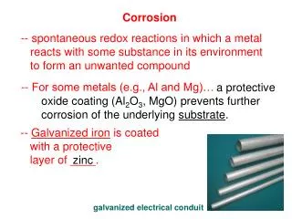
CREVICECORROSION Narrow openings, gaps, spaces, pores etc. between metal-metal components or metal-non-metal components may provoke localized corrosion. NOTE: unintentional crevices (seams, cracks etc.) can also act in the same way Passive alloys (especially stainless steels) are more vulnerable than more active alloys.
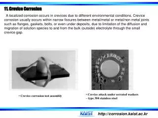
Crevice corrosion at a metal-to-metal crevice site formed between components of type 304 stainless steel fastener in seawater
Crevice Corrosion occurring on a Test specimen of Type 316 SS (Stainless Steel) in Acid CondensateZone of a Model SO2Scrubber.
Crevice corrosion is caused by the existence of small volumes of stagnant (corrosive) solution. Small holes, gasket surfaces, lap joints, bolt or rivet heads, nuts, washers, surface depositsall can cause C.C. (Crevice Corrosion). • Type 304 SS sheet can be cut by stretching a rubber band around it, immersing it in seawater (Fontana). The crevice between the rubber and the metal acts as the cutting zone.
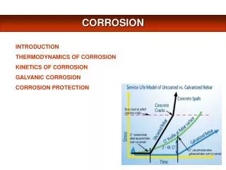
MECHANISM • Consider riveted metal section, immersed in aerated seawater (pH 7) e.g. stainless steel • Although O2 within crevice is rapidly used up, corrosion continues, controlled by overall cathodic reaction outside the crevice. • Tendency to build up M+ within the crevice must be balanced by -ve charge diffusing in. • Some OH- diffuses in, alot of Cl- diffuses in(OH- more mobile, c.f. FONTANA* … less of it).
MECHANISM Oxidation:MM+ + e- Reduction: O2 + 2 H2O + 4 e-4 OH- *FONTANA says Cl- more mobile … this is wrong.
Most metal ions (except alkali metals) hydrolyze: M+ + H2OMOH + H+ • Both Cl-and H+ accelerate metal dissolution (Cl-breaks down oxide, also H+partly responsible). • NOTE: there is now the possibility for H2 evolution within the crevice . . . . maybe! • NOTE: solution within crevices exposed to neutral dilute NaCl has been seen to have 3-10x [Cl-] in bulk, pH of 2-3.
Geometrical Type of crevice: metal to metal nonmetal to metal Crevice gap (tightness) Crevice depth Exterior to interior surface area ratio Metallurgical Alloy composition: major elements minor elements impurities Passive film characteristics Electrochemical reactions: Metal dissolution O2 reduction H2evolution Factors that can affect Crevice Corrosion resistance of stainless steels
Environmental Bulk solution: O2 content pH chloride level temperature agitation Mass transport, migration Diffusion and convection Crevice solution: hydrolysis equilibria Biological influences
CREVICE CORROSION OF CU ALLOYS different from that of SS; attack occurs OUTSIDE the crevice “Crevice corrosion” of Alloy 400 (70 Ni - 30 Cu) after 45 Days in Natural Seawater
Cathodic conditions inside crevices of Cu alloy have been inferred from observations of deposited Cu metal (where?). • “Differential metal-ion concentration” has been invoked as the mechanism; greater concentration inside the crevice raises the potential and makes it more noble than the outside. • Also, variant of the oxygen depletion mechanism has been invoked. • Clearly the situation is complex. • NOTE: ALL MATERIALS ARE SUSCEPTIBLE TO C.C. (CREVICE CORROSION), GIVEN NARROW CREVICES, POSSIBILITY OF CONCENTRATING IONS, DIFFERENTIAL AERATION CELLS, DIFFERENTIAL METAL CONCENTRATION CELLS, ETC.
COMBATING CREVICE CORROSION (after Fontana) Methods and procedures for combating or minimizing crevice corrosion are as follows: • Use welded butt joints instead of riveted or bolted joints in new equipment.Sound welds and complete penetration are necessary to avoid porosity and crevices on the inside (if welded only from one side). • Close crevices in existing lap joints by continuous welding, caulking, or soldering. • Design vessels for complete drainage; avoid sharp corners and stagnant areas.Complete draining facilitates washing and cleaning and tends to prevent solids from settling on the bottom of the vessel.
COMBATING CREVICE CORROSION (after Fontana) • Inspect equipment and remove deposits frequently. • Remove solids in suspension early in the process, if possible. • Remove wet packing materials during long shutdowns. • Provide uniform environments, if possible, as in the case of backfilling a pipeline trench. • Use "solid," nonabsorbent gaskets, such as Teflon, wherever possible. • Weld instead of rolling in tubes in tube sheets.
FlLIFORM CORROSION • Although not immediately apparent, filiform corrosion(filamentary corrosion occurring on metal surfaces) is a special type of crevice corrosion. • In most instances it occurs under protective films, and for this reason it is often referred to as underfilm corrosion. • This type of corrosion is quite common; the most frequent example is the attack of enameled or lacquered surfaces of food and beverage cans that have been exposed to the atmosphere.The red-brown corrosion filaments are readily visible.
Filiform corrosion usually on metals covered with thin organic film (0.1 mm)BUT also reported for: • steel; • magnesium; • aluminum; • tin; • silver; • gold; • phosphate; • enamel; • as well as with organics (lacquer, paper;seen on paper-backed Al foil, between metal and paper).
A lacquered steel can lid exhibiting filiform corrosion showing both large and small filaments partially oriented in the rolling direction of the steel sheet.Without this 10 x magnification by a light microscope, the filiforms look like fine striations or minute tentacles; (often mistaken for biologically – induced corrosion).
Attack usually occurs when relative humidity between 65 and 90%; has been seen at lower R.H. (Relative Humidity). • Average filament width 0.05 - 3 mm .. depending on coating (thickness, porosity, etc.), R.H., and corrosiveness of environment (presence of SO2, H2S, etc.). • Filament height 20 m.Growth rates observed between 0.01 mm/d and 0.85 mm/d. • Filaments are like minute tunnels, full of corrosion products.
Liquid in “head” is typically acidic. . . .pH 1- 4. • IN ALL CASES.... O2 (or air) and water are needed to sustain filiform corrosion … indicates a form of a DIFFERENTIAL AERATION CELL. Discuss: differential aeration cell concentration cell.
An aside on differential aeration . . (differential) concentration cell remember example: remember Cu - alloy crevice: Attack usually begins at imperfections in coating e.g., cuts, knicks, pores, etc. CO2 can stimulate process by dissolving in water carbonic acid. Chlorides, SO42-, S2- which can dissolve in condensing atmospheric moisture also increase attack. Optimum temperature for filiform attack between 20 & 35C. (potential log [Cu+])
Effect of humidity on filiform corrosion of enameled steel Relative humidity, %Appearance 0-65 No corrosion 65-80 Very thin filaments 80-90 Wide corrosion filaments 93 Very wide filaments 95 Mostly blisters, scattered filiform 100 Blisters Source:M. Van Loo, D. D. Laiderman, and R. R. Bruhn, Corrosion, 9:2 (1953). Appearance: Schematic diagram of a corrosion filament growing on an iron surface (magnified).
Schematic diagrams illustrating the interaction between corrosion filaments: (a) Reflection of a corrosion filament; (b) splitting of a corrosion filament; (c) joining of corrosion filaments; (d) “death trap”.
Mechanism Head supplied with H2O by osmosis (high concentration of Fe2+ inside) through coating and from precipitated hydroxide/oxide. Oxygen reduction creates hydroxide;precipitation creates corrosion product tail. . . . further oxidation to Fe3+ oxide etc. Hydrolysis of salts in head creates acidic conditions. Details of mechanism not understood…………. e.g., why do filaments “reflect” off other filaments? etc.
Filiform Corrosion on PVC-Coated Al Foil Advancing head and cracked tail of a filiform cell. Scale: 0.125 mm Gelatinous corrosion products oozing out of porous tail section. Scale:1.25 m
Close-up of the advancing head shown in adjacent figure.Minute cracks can be seen at the head/tail interface of a filiform corrosion cell.These cracks are entry points for water and air to provide a source of hydroxyl ions and an electrolyte.Intermediate corrosion products are just beginning to form in the head, and they undergo further reaction to form an expanded tail.The tail region is a progressive reaction zone that ultimately forms spent corrosion products.Between the head and porous end, ions gradually react with water and oxygen and are slowly transported in the direction of the tail to form final corrosion products. Scale:15 m
Prevention NOT EASY.... • store coated metals in dry air; • use more brittle films . . . these should crack at head and destroy differential aeration; • use impermeable coatings.
Pitting Corrosion PITTING:Extreme localized attack, may perforate metal sheet/plate . . . etc. “Pitting factor” = d = average penetration from weight loss; p = deepest penetration “Undercutting” pit opening usually < 1 mm. Pits may overlap to give the appearance of rough, general wastage.
Pitting is an insidious and destructive form of corrosion: • difficult to detect (pits may be small on surface, but extensive below surface from undercutting; may be covered with deposit); • can cause equipment to fail (by perforation) with very little weight loss; • difficult to measure as pit depth and distribution vary widely under (nominally) identical conditions; • “incubation” period may be months or years.
Pitting of stainless steel condenser tube. Pitting of 18-8 stainless steel by acid-chloride solution.
Pits usually occur on upward-facing horizontal surfaces, andless frequently onvertical surfaces; rarely on downward-facing surfaces; pit growth pit growth Gravity is involved. pit growth
Mechanism:Has some features in common with CREVICE CORROSION.... consider metal M being pitted by aerated NaCl solution... Autocatalytic processes occurring in a corrosion pit.
Remember: • inside pit - anodic, rapid dissolution; • outside pit - cathodic, O2 reduction; • most M+ will hydrolyse, form H+; • positive charges attract Cl-ions; • H+ and Cl-accelerate metal dissolution; • high ionic concentrations in pit make O2 solubility very low; • high density of solution within pits means pits are more stable when growing downwards; • static environment accelerates process.
At high pH (i.e.,high OH-concentration), precipitation of iron hydroxides and oxidation to Fe3+ oxides can lead to corrosion product caps or tubes around pits on steels. Corrosion tube growth mechanism.
Metals Susceptible to Pitting Most often, passivating metals, especially stainless steels, often in passivatingenvironments (e.g., containing oxygen) but with agents such as Cl- that attack the passive oxide film. SENSITIZED SS particularly vulnerable (its heat treatment has depleted the grain boundaries of Cr by precipitating chromium carbide). COLD WORKING increases pitting attack, perhaps dislocation pattern is important. DISCUSS ETCHED or GROUND surfaces more likely to pit than polished surfaces. Stainless Steel more susceptible than Carbon Steel (though CS will have more rapid GENERAL CORROSION).
Some alloys developed especially to resist pitting. Effects of alloying on pitting resistance of stainless steel alloys ElementEffect on pitting resistance ChromiumIncreases NickelIncreases MolybdenumIncreases SiliconDecreases; increases when present with molybdenum Titanium and niobium Decreases resistance in FeCI3, other mediums no effect Sulfur and selenium Decreases CarbonDecreases, especially in sensitized condition Nitrogen Increases Source: N. D. Greene and M. G. Fontana, Corrosion 15:25t (1959).
PittingEnvironments Usually, solutions containing chloride or chlorine-containing ions (e.g., hypochlorites [bleaches]) have strong pitting tendencies. Bromides are also aggressive, but fluorides and iodides are not. Cupric, ferric and mercuric ions promote pitting . . . easily reduced cathodically and do not require dissolved O2; CuCl2 and FeCl3 are extremely aggressive (latter used as a test solution). Thiosulphate ion (S2O32-) may also promote pitting.
Evaluating Pitting Attack Weight loss of test specimens no good ( . . . why ?). Measurement of pit depth complicated because of statistical variations. Average pit depth of little use, since it isthe deepest pit that causes failure. Relationship between pit depth and the number of pits appearing on a corroded surface.
MAXIMUM PIT DEPTHcan be a useful way of expressing pitting corrosion, and for comparing pitting resistance of standard test samples. HOWEVER, statistical nature of pitting means that sample size is important. Should never predict lifetime of plant components from tests on small samples. Pit depth as a function of exposed area.
Examples of pitting corrosion: • Alloy-800 SG tubes with phosphate chemistry…pitting severe pitting wastage. Point Lepreau had some pitting, switched to AVT. • SS cooling water H.X. left static under silted conditions…severe pitting; replaced with Ti plate-type. • Others?