Download
1 / 2
20 likes | 197 Views
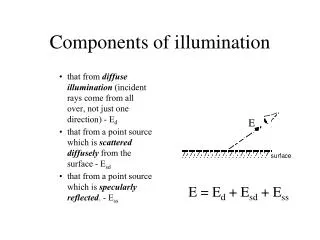
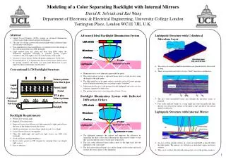
Lightguide Structure with Cylindrical Microlens Layer Two arrays of convex cylindrical microlenses are placed directly above each grating. These are separated vertically to form a “thick” microlens combination. The first order transmitted beams pass through the microlens arrays as required.

E N D
Lightguide Structure with Cylindrical Microlens Layer • Two arrays of convex cylindrical microlenses are placed directly above each grating. • These are separated vertically to form a “thick” microlens combination. • The first order transmitted beams pass through the microlens arrays as required. • First order reflected beams at a steep angle pass into the guide and then directly out of the lower surface of the guide as they are below the critical angle for reflection. Lightguide Structure with Internal Mirror • An array of thin metallic mirrors in a layer are embedded or placed within the light guide. The mirrors are reflective on both their upper and lower surfaces. • They serve to reflect the reflected grating orders out of the grating windows. Modeling of a Color Separating Backlight with Internal MirrorsDavid R. Selviah and Kai WangDepartment of Electronic & Electrical Engineering, University College LondonTorrington Place, London WC1E 7JE, U.K. Abstract • Liquid Crystal Displays (LCDs) require an advanced illumination system to give high contrast and power efficiency. • The aim is to design a power efficient backlight which collimates light rays normal to the display. • Non-sequential ray trace modelling is a potential tool for the design of the total internal reflection (TIR) backlight. • Light emitted from red, green and blue chip LEDs enters the multimode lightguide emerging at periodic grating coupler "windows“ but some light is lost out of the bottom of the guide. • An array of micro-mirrors within the guide compensates for this loss. • Our model allows us to optimize the distance of the micro-mirrors from the grating windows, the mirror size and guide dimensions to give improved optical uniformity and efficiency. Conventional LCD Backlight Structure Backlight Requirements • Wider LCD viewing angle • Higher LCD contrast ratio • Improved conversion efficiency of light generated to light emitted from the front of the display towards the viewer • Ideally no polarizers or colour filters which absorb a lot of light • Lower electrical power consumption • Thin, flat, lightweight and small size light source, e.g. LED with backlight • Good uniformity and high brightness • Better colour gamut on CIE diagram by adopting three wavelength light sources • Easy to fabricate Advanced Ideal Backlight Illumination System • Illumination of a set of three red, green and blue pixels. • This micro-optical system is replicated many times to form an array along the length of the light guide. • The light guide has on its upper surface a periodic array of discrete gratings each of limited extent which act as grating coupler “windows”. • Light periodically exits at the grating from the lightguide and colors are also angularly separated by diffraction. • The grating surface has a very fine pitch of about 0.5 µm. Backlight Illumination System with Reflected Diffraction Orders • The lightguide optimizes the contrast and improves the efficiency by separating the three colors and collimating the three narrow beams so that they pass through the centre of each pixel respectively. • The zero order diffracted beam reflects most of the light back into the lightguide at the same angle. • The first order reflected beams are a mirror image of first orders and travel towards the lower surface of the lightguide. 1
Depth of mirror d (m) Number of rays leaving through grating Width of mirrors, w (m) (100 sampling point) Number of rays leaving outside of the grating apertures log ( depth of mirrors, d ) (m) 990m Micro-mirrors Rays Rays Micro-mirrors Lightguide Lightguide Acknowledgements • The authors want to thank the IEE for awarding K.Wang a Research Scholarship • The authors acknowledge technical support from Breault Research Organization, Inc. for use of the modeling CAD package ASAP 7.1.8. • The authors thank T. Kataoka from the Department of Electronic & Electrical Engineering, University College London for helpful theoretical discussions on the structure of nematic liquid crystal. • We would also like to thank the SID reviewer of this paper for giving helpful advice and thank the SID for awarding K.Wang Student Travel Grant. Number of rays leaving through grating Number of rays leaving from opposite side of the lightguide Width of mirrors, w (m) Cylindrical Microlens • We use two cylindrical microlens arrays which give more design variables to enable optimization of collimation. • The microlenses convert the angular separation of the three color beams into a spatial separation and collimate the beams so that they provide illumination normal to the LCD and separate them sufficiently and narrow the beams so that they pass thorough the centre of each corresponding LCD pixel. Total Internal Reflection (TIR) Lightguide • The total internal reflection light guide is fabricated without cladding, from a transparent polymer with a refractive index of 1.50 giving a critical angle by the formula, of • The light generated from LEDs enters the lightguide, the angular distribution of rays is bound within • Tracing back the critical ray at the lightguide side wall to the entrance face of the guide, the refractive angle of the ray at the internal surface of the lightguide is , which is larger than . • According to Snell’s Law, all rays incident on the entrance of the lightguide at angles less than will strike the interior wall at angles greater than and so will be totally internally reflected and will travel along the lightguide. • This means that all beams incident on the input face of the guide are guided. Position and Width of Micro-mirror Array • We modeled the full backlight structure so that the optimum size, position and width of the micro-mirrors could be established for this backlight structure. To Establish the Optimum Depth of the Micro-mirror Array • We fixed the width of the mirrors and varied the depth. • When the mirrors move from the upper surface to the lower surface of the light guide, the number of rays leaving the guide at the grating increased. • When the micro-mirrors were placed deeper than 10 µm some light exited the lightguide at the top surface but outside the grating region. • Mirrors too close to the upper lightguide surface can block the light from reaching the grating “windows” so the output is reduced. • In the range of mirror depths, d = 0 to 10 m, the maximum output occurs at 10 m. • The best position was found to be at 10 m which is a conveniently small figure to envisage realistic fabrication procedures for this internal or embedded micro-mirror array layer. To Establish the Optimum Width of the Micro-mirror Array • We fixed the mirror depth at the optimum of 10 m below the upper surface of the light guide and varied the width from the minimum of 0.1 m to the maximum of 331 m. • If the width is set to be too small, some first order reflected light passes through the gaps between the micro-mirrors and exits the lower surface of the guide. • If the mirror is too wide it will block the rays from the light guide from reaching the grating and so reduce the rays reaching the LCD cutting down the brightness and efficiency. • The optimum mirror widths were found to be at 160 ± 3 m, to give the maximum output. Micro-mirror Depth/Width Coupling • In fact the micro-mirror depth and width are coupled in their effects and so cannot be correctly considered independently of each other. • We have calculated and plotted a contour map showing their inter-relationship. The optimum occurs at the marked point at • The contour plot shows that the light at the LCD panel at this point increases by 38.2% ( ). Air Air n=1.5 n=1.5 Conclusions • A thin, efficient backlight illumination system was modeled and designed which did not require the usual power absorbing colour filters. • A micro-mirror array layer inside the multimode lightguide reduces the light lost from the opposite side of lightguide improving light intensity by 38.2% • A microlens system was designed to collimate and to direct the light normal to the display for optimum contrast. • Periodic, limited length, discrete gratings are used instead of a continuous grating surface. It also allows us to control the strength of each grating window individually to abstain better uniformity. Requirement Model 2