Design and Implementation of Muon Cosmic-ray Shower Trigger System
This joint design work by Napoli and Padova groups presents the trigger system for segmenting and selecting muon cosmic-ray showers, detecting low energy electrons, and defining pixels for the T600 detector. The system architecture involves the Local Trigger Control Unit (LTCU) and Trigger Supervisor, with functionalities like discriminating inputs, generating trigger proposals, and monitoring trigger rates. The LTCU prototypes (v1.0 and v2.0) have been tested on Geneva prototypes, demonstrating features such as channel masking, threshold setting, trigger rate monitoring, and discriminator testing. Test results show trigger efficiency and performance measurements, with LTCU v2.0 undergoing EM/RF screening for enhanced functionality. The study concludes with the production of LTCU v2.0 boards, ready for testing on detector prototypes, ongoing data analysis, and article preparation.

Design and Implementation of Muon Cosmic-ray Shower Trigger System
E N D
Presentation Transcript
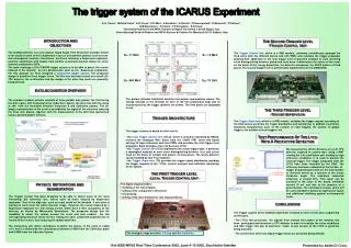
ICARUS General Trigger Design Work jointly conducted by Napoli and Padova groups Contributions from: M.Della Pietra, A.Di Cicco, P.Di Meo, G.Fiorillo, P.Parascandolo, R.Santorelli, P.Trattino B.Baboussinov, S.Centro, F.Pietropaolo, S.Ventura
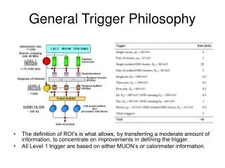
Segmentation and Selectivity Muon Cosmic-ray shower Low energy electrons
T600 pixel definition T600 Half Module – 1 chamber viewed from cathode Rack 13 Rack 11 Rack 20 Rack 1 864 mm 32 x 9 Induction II wires 32 x 9 Collection wires 1 pixel area: ~ 0.6 m2 Total Number of Pixels ~ 80
MC simulation: low energy events ICAFLUKA, special thanks to G. Battistoni)
MC simulation: high energy events ICAFLUKA, special thanks to G. Battistoni)
Trigger Input • PMTs • DAEDALUS • AWS (Analog wire sum) • External (beam profile chambers, cern-spill, …)
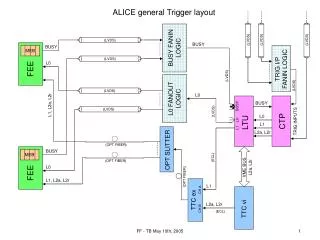
Trigger system architecture • LTCU: discriminates the 18 inputs, has one independent threshold for each input, gives two trigger proposal as output; • TCU: performs coincidences between LTCUs proposals, processes the fired pixels to study and label the event topology, requests global or local trigger; • Trigger Supervisor: monitoring of the trigger and the DAQ system, statistical functions.
The Local Trigger Control Unit prototype targets • discriminate the inputs, coming from the v791 boards; • give as output two separate trigger proposals to the next level, one for Induction II and one for Collection; • remote control of all the board’s functionalities; • discriminators check-control; • trigger rate measurements for each input.
The LTCU prototype v1.0 VDAC IN Voltage follower IN OUT Discriminator RC filter Power supply FPGA Input stage DAC 10 MHz oscillator Trigger outputs 18 inputs RS232 interface
The LTCU functionalities v1.8i • Mask the input channels; • Read the mask status; • Set the thresholds; • Monitor the trigger rate for each input; • Discriminator test mode; • Select one discriminator output put on front panel. All the board functionalities are remotely controlled via RS232 interface.
Trigger rate test chain V789 V816 • LTCU inputs = 4 S signals from collection plane; • Trigger generated from only one S input (no FastOR); • LTCU trigger output distributed to V816 module. IN trigger IN IN IN IN IN IN IN IN V791 Ind Coll LTCU OUT OUT OUT OUT OUT OUT OUT OUT OUT LTCU Trigger OUT S S S S IN PC (RS232) Analog S OUT
Trigger Rate Plateau (I) Plateau zones
Trigger Rate Plateau (II) Plateau zones
Trigger efficiency test chain V789 V816 • LTCU inputs = 4 S signals from collection plane; • One LTCU IN and Trigger OUT digitalized by a modified V791; • PMT trigger distributed to V816 module. IN trigger PMT IN IN IN IN IN IN IN IN Modified V791 V791 Ind Coll LTCU OUT OUT OUT OUT OUT OUT OUT OUT OUT OUT S S S S IN IN IN PC (RS232) Analog S OUT
VTH VTest VREF or IN VTH IN VREF Band-pass filter Selectable inverter (G=1) DAC (for one channel) OUT Filter for low noise performance Input stage (for one channel) Power supply an filter Stable 259mV tension circuit VREF for DAC LTCU prototype v2.0 EM/RF Screening for input stage
PWR and GND distribution for LTCU v2.0 Four GND and two PWR planes VCC, DGND (V791 digital stage) +5A1,AGND1 (V791 mux stage) ±5A,AGND (V791 preamp. stage)
Conclusions • LTCU v2.0 is being produced (5 boards); • Ready to be tested on detector prototypes; • Analysis of test data in progress; • Article in preparation.