Advanced Computer Architecture Lecture 15
230 likes | 439 Views
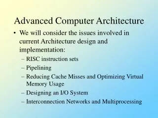
Advanced Computer Architecture Lecture 15. Project 4 review Cache design example. Project 4 team review. Team Dog. Cache design example. CPU: B2Logic model Memory 256 x 8, RAM (no ROM) 4X slower then cache, Rdy signal Cache: direct mapped, write-through Data: 16 x 8, RAM (no delay)

Advanced Computer Architecture Lecture 15
E N D
Presentation Transcript
Advanced ComputerArchitectureLecture 15 Project 4 review Cache design example University of Portland School of Engineering
Project 4 team review • Team Dog University of Portland School of Engineering
Cache design example • CPU: B2Logic model • Memory • 256 x 8, RAM (no ROM) • 4X slower then cache, Rdy signal • Cache: direct mapped, write-through • Data: 16 x 8, RAM (no delay) • Tag: 16 x 4 RAM (no delay) University of Portland School of Engineering
System schematic University of Portland School of Engineering
7 4 3 0 Memory address from CPU Tag Index written to cache tag bits indexes cache Addressing University of Portland School of Engineering
256 x 8 Address A 8 Data Din Rdy 8 Dout Mrw# R/W# Ram memory Rdy asserted when memory access complete University of Portland School of Engineering
RAM schematic Rdy indicates access time complete G1 initiates a memory operation University of Portland School of Engineering
Main Driver Control Driver Cache General memory design R/W# System Bus enable enable hit R/W# University of Portland School of Engineering
Find cache block diagram? Trw# Hit Address 8 Data 8 Crw# University of Portland School of Engineering
Controller description • Read hit: read cache data and drive it onto bus • Write hit: write data/tag into cache and data into memory • Read miss: read data from memory, drive it onto bus, write data/tag into cache • Write miss: same as write hit (we will use this fact later in the design) University of Portland School of Engineering
Find controller inputs? • Hit (not miss) • Ready • Adr • Data • Read/wr# University of Portland School of Engineering
Find controller outputs? • Ack • Cache r/w# • Tag r/w# University of Portland School of Engineering
Miss Read Hit Write Ready Ready Ready Ack Ack Ready Memop Ack Reset Intuitive approach State diagram 1 Difficult to assign adjacent states University of Portland School of Engineering
1001 ReadHit ReadMiss Write 0101 0001 0011 Ready Ready Ready 1000 Ready Ack Memop 0010 Ack 0000 0100 Ack Reset Correct, far from optimal State diagram 2 University of Portland School of Engineering
Collapsing states • Objective: • High speed • Simple design • Combine states: fewest to solve problem • Write • Read hit • Read miss Minimal or optimal University of Portland School of Engineering
c d 000 b Reset Find optimal state diagram? Read hit Read miss Write University of Portland School of Engineering
16 x 4 tag Trw# R/W# Dout Match Din 4 high 4 A Hit 4 high low 4 16 x 8 cache Address A 4 8 low Data Din 8 Dout R/W# Crw# Find cache block diagram? University of Portland School of Engineering
Find controller inputs? • Reset, clock: standard definitions • Read: CPU executing a read • Write: CPU executing a write • Hit: upper address bits match with tag bits • Rdy: main memory has completed access University of Portland School of Engineering
Find controller outputs? • Mrw#: memory read, write • Mben: memory driving bus • Crw#: cache read, write (same as Trw#) • Cben: cache driving bus • Ack: acknowledge that memory ready University of Portland School of Engineering
Cache controller Mg1 Read Mrw# Write Mben Crw# Hit Cben Rdy Ack Controller block diagram University of Portland School of Engineering
Memory system schematic University of Portland School of Engineering