Download
1 / 21
210 likes | 407 Views
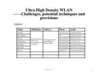
Multi-Cell Handover Architecture in Ultra-High-Throughput WLAN. Date: 2013-1 1 -3. Nov . 2013. Authors:. Slide 1. Content. Nov . 2013. Slide 2. Motivation Proposed Multi-Cell Handover Architecture in Ultra-High-Throughput WLAN Network topology Handover scenario Handover process

E N D
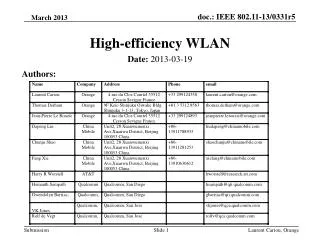
Multi-Cell Handover Architecture in Ultra-High-Throughput WLAN Date: 2013-11-3 Nov. 2013 Authors: Slide 1
Content Nov. 2013 Slide 2 • Motivation • Proposed Multi-Cell Handover Architecture in Ultra-High-Throughput WLAN • Network topology • Handover scenario • Handover process • IP flow handover • Summary • References
Motivation Nov.2013 Slide 3 • In the network topology consisting of multi-cell overlapping coverage, the mobile terminals will perform the handover process frequently among the different Access Points (APs) in the multi-cell scenario because of the mobility of the user and poor cell coverage. • In order to ensure the continuity of the traffic and achieve better quality of service (QoS) requirement, it is very essential to carry the research on the handover architecture and mechanisms for the multi-AP handover in the overlapping coverage. 3 This proposal illustrates the multi-AP handover scheme based on a centralized control architecture from the perspective of traffic continuity and QoS requirement satisfaction.
Proposed Multi-Cell Handover Architecture in Ultra-High-Throughput WLAN Nov. 2013 Slide 4 • General Description • handover trigger decision • network information collection • TAP decision and selection • network information collection is regarded as the preparation for the TAP decision and selection, so the two stages will be presented together. • handover execution • The handover trigger decision • triggered by RSS (Received Signal Strength) and QoS requirements (user-centric decision and trigger strategies) • triggered for load balancing (triggered and decided by the SAP) • triggered due to the disconnection at the cell’s border (SAP’s coverage makes handover trigger and decision)
Proposed Multi-Cell Handover Architecture in Ultra-High-Throughput WLAN Nov. 2013 • TAP decision and selection • channel detection process in the cells • CAP collects the idle channel information from all cells • UE/SAP/CAP decides and selects TAP • Handover execution • system synchronization, • random access and • capability negotiation Slide 5
Network topology of multi-cell handover architecture in Ultra-High-Throughput WLAN Nov. 2013 • Network topology • AP of each cell serves all the users in the cell • The CAP uniformly manages all APs in the centralized control mode • The CAP collects the real-time network parameters and provides the necessary information for the cross-cell handover decision • The server uniformly manages all CAPs in the centralized control mode for L3 layer handover Slide 6
Handover scenario of multi-cell handover architecture in Ultra-High-Throughput WLAN Nov. 2013 • Handover scenario • UEi moves through the overlapping multi-cell and performs the horizontal handover among the different TAPs. • The received signal strength at the UEi is less than the preset threshold, the handover mechanism will be initiated between the APs. Slide 7
Handover flow of multi-cell handover architecture in Ultra-High-Throughput WLAN Nov. 2013 • Handover trigger and decision • handover trigger and decision is made by UEi(consisting of RSS trigger mode and QoS requirements trigger mode). Decided by UEi according to current received signal strength at UEi from SAP or the user's QoS level requirement. . • handover trigger and decision is made by SAP (load balancing trigger mode): this mode is applied to the case of considering network load balancing and is implemented by bidirectional dynamic load transfer. Decided by the SAP and CAP according to the current network load situation (the number of the idle channel can be referred to). • handover trigger depends on the SAP’s coverage (disconnection at cell’s border trigger mode): the AP is configured as a continuous online cell and maintain connection with the SAP until UEi is out of the SAP’s coverage and disconnect with SAP automatically. Slide 8
Handover flow of multi-cell handover architecture in Ultra-High-Throughput WLAN Nov. 2013 • TAP decision and selection Including network parameters collecting and TAP decision and selection. • idle channel detection process in the single cell If the channel is in use, the signal energy of this channel will exceed preset threshold; if the channel is idle, the signal energy of this channel will be lower the preset threshold. Slide 9
Handover flow of multi-cell handover architecture in Ultra-High-Throughput WLAN Nov.2013 Idle channel detection process in the single cell Slide 10
Handover flow of multi-cell handover architecture in Ultra-High-Throughput WLAN Nov. 2013 • The CAP collects idle channel information from all cells by using request-response mode. Slide 11 • TAP decision and selection
Handover flow of multi-cell handover architecture in Ultra-High-Throughput WLAN Nov.2013 Slide 12 • TAP decision and selection • UE/SAP/CAP makes a decision to select the TAP • The UE makes the decision to select the TAP by performing idle channel information collection in a centralized mode and making a handover decision in a distributed mode • The SAP makes the decision to select the TAP and notifies the UE in the end by using semi-centralized decision handover mode • The CAP makes the decision to select the TAP according to the idle channel information of all cells, and then notifies the SAP, the handover UE and the selected TAP by using a fully centralized decision handover mode
Handover flow of multi-cell handover architecture in Ultra-High-Throughput WLAN Nov. 2013 Slide 13 • Handover execution by UE • UE sends a request to the SAP for initiating a handover • The SAP notifies the TAP to prepare for the resources the UE needs after the handover • The UE completes the handover to the TAP with the assistance of the SAP • After the SAP disconnects the line with the UE, UE will access to the selected TAP according to a new access process consisting of three stages: system synchronization, random access and capability negotiation
Nov. 2013 Handover execution process Slide 14
IP flow handover between SAP, TAP and CAP Nov. 2013 Slide 15 • L2 layer handover • L2 layer handover refers to the IP flows handover between SAP and TAP and happens between different APs in the same IP subnet. • The L2 layer handover includes following three stages: the acquisition of network topology, handover decision and execution, the network re-entry.
IP flow handover between SAP, TAP and CAP Nov. 2013 Slide 16 • L3 layer handover • L3 layer handover refers to the IP flows handover between different CAPs, namely, the IP flow handover between different APs in different IP subnet or different connection service network. • If the handover process involves the change of the CAP, the Mobile IP will be used to ensure the continuity of the IP layer connection after L2 layer handover (MAC layer and the physical layer handover) is completed.
IP flow handover between SAP, TAP and CAP Nov. 2013 Slide 17 • L3 layer handover • the network layer sends a routing request message (RS) to NCAP and NCAP sends a router announcement message (RA) to respond. • the UE can obtain one or multiple new link addresses as its foreign agent care-of address • The UE will select one of the newly generated care-of addresses as its primary care-of address and send a binding update message (BU) to the home agent, and then establish the binding between home address (HOA) and care-of address (CoA) in the home agent.
Summary Oct. 2013 Slide 18 • This proposal illustrates the multi-AP handover scheme based on a centralized control architecture from the perspective of traffic continuity and QoS requirement satisfaction. • The proposal presents a network topology architecture for the handover execution, describes the general handover scenario, designs the handover mechanism and processes for the multi-AP handover in the general handover scenario. • The IP layer handover schemes are illustrated, which consists of L2 layer handover and L3 layer handover. • The QoS requirements and network parameters can be collected from the proposed handover architecture for making the handover decision, which can avoid the communication interruption and Ping-Pong effect.
IP flow handover between SAP, TAP and CAP Nov. 2013 Slide 19 • L3 layer handover • After the binding update with HA is completed, a bidirectional data transmission tunnel is established between the HA and the UE. The HA can send the intercepted IP datagrams sent to the mobile node's home address to the UE through the tunnel. • the user will send a correspondent binding request to the correspondent node, which will identify the legitimacy and send the binding acknowledgment message BACK. • the correspondent node will send the IP datagram directly to the user's care-of address instead of sending to the user's home link
References Nov. 2013 Slide 20 • [1] IEEE 802.11a Wireless LAN Medium Access Control (MAC) and Physical Layer (PHY) specifications: Higher Data Rate Physical Layer Specifications in the 5GHz Band • [2] IEEE 802.11b Wireless LAN Medium Access Control (MAC) and Physical Layer (PHY) specifications: Higher Data Rate Physical Layer Extension Specifications in the 2.4GHz Band • [3] IEEE 802.11g Wireless LAN Medium Access Control (MAC) and Physical Layer (PHY) specifications: Higher Data Rate Physical Layer Further Extension Specifications in the 2.4GHz Band • [4] IETF RFC768 User Datagram Protocol • [5] IETF RFC791 Internet Protocol • [6] IETF RFC793 Transmission Control Protocol • [7] SJ/T 11312-2005 Specification for home backbone-network communication protocol • [8] SJ/T11314-2005 Specification for home sub-network communication protocol • [9] YD/T 2394.2—2012 High spectrum efficiency and high throughput wireless LAN technical requirements - Part2: Medium access control (MAC) and physical layer (PHY) specifications for enhanced ultra high throughput wireless local area network • [10] IEEE 802.16-2004: IEEE Standard for Local and Metropolitan Area: Networks-Part 16: Air Interface for Fixed Broadband Wireless Access Systems • [11] IEEE 802.16e-2005: IEEE Standard for Local and Metropolitan Area: Networks-Part 16: Air Interface for Fixed and Mobile Broadband Wireless Access Systems
Nov. 2013 Thank YOU Slide 21