Chapter 20 Circuits and Circuit Elements
Chapter 20 Circuits and Circuit Elements. Schematic Diagram. Schematic diagram-diagram that depicts the construction of an electrical apparatus . Schematic Diagram. Reading schematic diagrams is necessary to determine how the parts in an electrical device are arranged.

Chapter 20 Circuits and Circuit Elements
E N D
Presentation Transcript
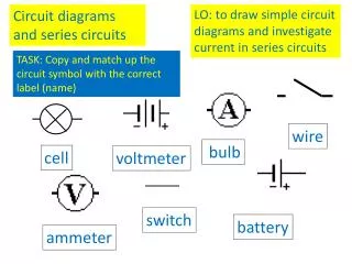
Schematic Diagram • Schematic diagram-diagram that depicts the construction of an electrical apparatus
Schematic Diagram • Reading schematic diagrams is necessary to determine how the parts in an electrical device are arranged. • Each element in a piece of electrical equipment is represented by a symbol.
Electric Circuit • Electric circuit - path through which charge can be conducted • Schematic diagram for a circuit is called a circuit diagram. • Load - any element or group of elements in a circuit that dissipates energy
Electric Circuit • Simple circuit - consists of a source of potential difference and electrical energy, such as a battery, and a load, such as a bulb.
Closed circuit - circuit with a closed loop path for electrons to follow • Switch must be closed for a steady current • Open circuit - circuit with an incomplete path, therefore no charge flow and charge current
Light bulbs contain a complete conducting path • Filaments in a light bulb have two separate contacts with the socket
Light bulbs contain a complete conducting path • One is in the bottom of the socket and is connected one side of the filament (a) • Other is on the side of the socket and is connected to the other side of the filament (c)
Charges from the socket enter through the bottom, through the wire connected to the bottom, through the filament, then through the wire connected to the side of the socket, and exit the bulb through the threads.
Short Circuit • Short circuit - circuit without a load so it contains little resistance to the movement of charges. • When a wire is connected from one terminal of a battery to another by a wire with little resistance.
Short Circuit • Short circuits can occur in the wiring of your home • Most wires cannot stand increased current and can melt the insulation or cause it to catch fire.
EMF • Emf - the energy per unit charge supplied by a source of electric current. • Ex: batteries and generators • The source of potential difference and electrical energy is the circuit’s emf
EMF • Any device that increases the potential energy of charges circulating in a circuit is a source of emf. • The source acts as a “charge pump” forcing the electrons to move in a certain direction
Terminal Voltage • Batteries behave as if they contain both an emf source and a resistor. • Terminal voltage - the potential difference across the batteries terminals. • Slightly less then the battery’s emf.
Terminal Voltage • As charge moves through the circuit, it’s electrical potential energy is converted to other forms of energy. • Charge must gain as much energy as it loses in one complete trip. • Potential increase across the battery must equal the potential decrease across the load.
Resistors in Series • Series - describes a circuit or portion of a circuit that provides a single conducting path without junctions.
Resistors in Series • The equivalent resistance of a series combination is the sum of the individual resistances
Resistors in Series • The equivalent resistance is always greater than any individual resistance • The current in each resistor is the same • Series circuits require all elements to conduct
A 9.0 V battery is connected to four light bulbs, as shown below. Find the equivalent resistance for the circuit and the current in the circuit.
Resistors in Parallel • A wiring arrangement that provides alternative pathways for the movement of a charge is called parallel.
Resistors in Parallel • Resistors in parallel have the same potential differences across them • The sum of the currents in parallel resistors equals the total current
Resistors In Parallel • The equivalent resistance for a parallel arrangement of resistors must always be less than the smallest resistance in the group of resistors. • Parallel circuits do not require all elements to conduct.
When a bulb in a string of lights goes out not all of the lights goes out. • Because some circuits are arranged in parallel, appliance manufacturers are able to standardize their design, producing devices that operate at the same potential difference.
A 9.0 V battery is connected to four resistors, as shown below. Find the equivalent resistance for the circuit and the total current in the circuit.
Complex Resistor Combinations • Most circuits today use both series and parallel wiring to utilize the advantages of each. • i.e. household circuits
Complex Resistor Combinations • Outlets wired in parallel so all appliances operate independently • Fuses and circuit breakers wired in series to prevent excessive current.
Circuit Elements • Fuse – small metallic strip that melts if the current exceeds a certain value. Must be replaced after it has melted. • Circuit breaker – triggers a switch when the current reaches a certain value. The switch must be reset after the circuit overload has been removed.
Circuit Elements • The current in the fuse or circuit breaker is the same as the total current in the circuit.
Equivalent Resistance • To determine the equivalent resistance for a complex circuit: • you must simplify the circuit into groups of series and parallel resistors • Find the equivalent resistance for each group
Solve for Equivalent Resistance 1. Redraw the circuit as a group of resistors along one side of the circuit. For now, disregard the emf source and work only with the resistances. 2. Identify components in series and calculate their equivalent resistance. Redraw the circuit.
Solve for Equivalent Resistance 3. Identify the components in parallel, and calculate their equivalent resistance. Redraw the circuit. 4. Repeat steps 2 and 3 until the resistors in the circuit are reduced to a single equivalent resistance. 5. Redraw the circuit with the equivalent resistance connected to the original emf source.
Determine the equivalent resistance of the complex circuit shown below.
Solve for Current and Potential Difference • Work backward to find the current in and the potential difference across a part of a circuit • There is no single formula – must apply the rules to smaller pieces of the circuit until the desired values are found.
Solve for Current and Potential Difference 1. Determine the equivalent resistance of the circuit. (We’ve already done this.) 2. Calculate the total current in the circuit.
Solve for Current and Potential Difference 3. Calculate the current in and potential difference across each equivalent resistance. Repeat this process until the desired values are found.
Determine the current in and potential difference across each resistor.
Determine the equivalent resistance for the following circuit. Calculate the current in and the potential difference across resistor d. Ra = 8.0 Ω Rb = 4.0 Ω Rc = 6.0 Ω Re = 9.0 Ω 14.0 V Rd = 3.0 Ω Rf = 7.0 Ω