Download
1 / 10
100 likes | 226 Views
ATLAS L1 Calorimeter Trigger / DCS. ATLAS L1 Calorimeter Trigger Overview Signals monitored by DCS Implementation and current activities. ATLAS L1 Calorimeter Trigger. Pre-Processor: 8 crates, ~128 processors Jet/Enegy Processor: 2 crates, 36 processors

E N D
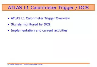
ATLAS L1 Calorimeter Trigger / DCS • ATLAS L1 Calorimeter Trigger Overview • Signals monitored by DCS • Implementation and current activities
ATLAS L1 Calorimeter Trigger Pre-Processor: 8 crates, ~128 processors Jet/Enegy Processor: 2 crates, 36 processors Cluster Processor: 4 crates, 64 processors All processors are VME- style modules, 9U×40cm Off-Detector
Data and control channels into DCS The L1 Calorimeter Trigger comprises a total of ~250 modules. Each of them needs to be monitored by DCS. Due to limited backplane connectivity only 2 pins per module are available for readout of environmental data. Therefore a local CAN node is required on each processor module. • ~ 8 supply voltages/processor board, either low resolution ADC or digital OV/UV detection only • ~ 8 temperatures/processor board, low resolution ADC (accurate to a couple of deg. Centigrade only) • Standard crate monitoring / control (1 CAN node per crate: voltages, temperatures, PWR on/off) • Sampling rate of ~1/minute might be sufficient Total amount of data into DCS: < 250 x 16 words
Requirements The processor boards are densely packed with components. All components have to adhere to the system-wide geographic address scheme • Inexpensive CAN node with low-accuracy A/D converter • Low consumption of board real estate • CAN node ID definition via external GeoAdd lines encoded on the backplane • Needs to fit into standard DCS environment • No rad-hard components required So as to reduce the number of CAN lines, crate-level CAN/CAN bridges are envisaged. A crate will look like a single can node from a SCADA point of view !
Implementation : (1) ELMB • CERN standard, full software / firmware support • Too large to fit on some of the processor modules • CAN node IDs cannot presently be read in from external lines (GeoAdd) at PwrUp • Only a tiny fraction of ELMB resources can be used Expensive
Implementation : (2) Fujitsu MB90595 • Single chip CAN node • Dual CAN version available (useful for CAN/CAN bridge) • On-chip ADC • Cheap • Low real estate consumption • Not firmware-compatible to ELMB write our own
Implementation : (3) ??? Can we find a single-chip approach which is compatible with the ELMB in terms of firmware and software? • Since it adheres to standards it could (?) be supported by CERN • Small enough to fit on all of the processor modules • CAN nod IDs could easily be read in from external lines (GeoAdd) at PwrUp • Inexpensive
Current Activities, Status The cluster processor prototype will carry Fujitsu CAN • A CAN/CAN bridge is being implemented on a „TCM“ module built at RAL • Hardware exists • Software being written at Queen Mary (QMUL) by Dave Mills, based on code kindly provided by NIKHEF The jet/energy processor prototype will carry an ELMB • A couple of ELMBs available for test at U. Mainz for tests The processor modules will go into combined tests in spring 2002