Download

1 / 57
570 likes | 707 Views
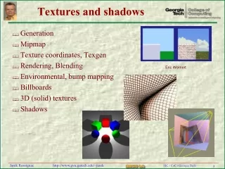
Appearance modeling: textures and IBR Class 17. 3D photography course schedule. Papers. http://www.unc.edu/courses/2004fall/comp/290b/089/papers/. Projects. Volumetric 3D integration. Multiple depth images. Volumetric integration. Appearance Modeling. Texturing Single image

E N D
Papers http://www.unc.edu/courses/2004fall/comp/290b/089/papers/
Volumetric 3D integration Multiple depth images Volumetric integration
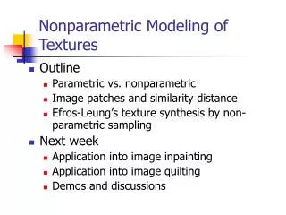
Appearance Modeling • Texturing • Single image • Multiple image • Image-based rendering • (Unstructured) lightfield rendering • Surface lightfields
Texture mapping 3D model Need to estimate relative pose between camera and 3D model
Texture Mapping • Conventional texture-mapping with texture coordinates • Projective texture-mapping
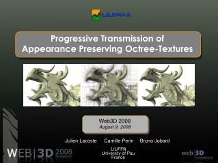
Texture Map Synthesis I • Conventional Texture-Mapping with Texture Coordinates • Create a triangular texture patch for each triangle • The texture patch is a weighted average of the image patches from multiple photographs • Pixels that are close to image boundaries or viewed from a grazing angle obtain smaller weights Photograph 3D Triangle Texture Map
Texture Map Synthesis II • Allocate space for texture patches from texture maps • Generalization of memory allocation to 2D • Quantize edge length to a power of 2 • Sort texture patches into decreasing order and use First-Fit strategy to allocate space First-Fit
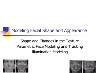
Appearance Modeling texture atlas
Dealing with auto-exposure (Kim and Pollefeys, CVPR’04) Photometric alignment of textures (or HDR textures)
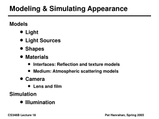
Image as texture Depth image Texture image Triangle mesh Textured 3D Wireframe model Affine vs. projective texture mapping (see later)
Lightfield literature • Plenoptic function • Lightfield (plane) and Lumigraph (some geometry) • Unstructered lightfield (some (view-dependent) geometry) • Surface lightfields (full geometry) • Plenoptic sampling (trade-off geometry vs. images) (Adelson&Bergen´91; McMillan&Bishop,Siggraph´95) (Levoy&Hanrahan,Siggraph´96 Gortler et al.,Siggraph´96) (Koch et al. ICCV´99; Heigl et al. DAGM´99; Buehler et al. Siggraph‘01) (Wood et al.,Siggraph´00, Chen et al., Siggraph‘02) (Chai et al.,Siggraph´00)
viewpoint surface focal surface Lightfield rendering Approximate light rays by interpolating from closest light rays in lightfield • Transfer from images to virtual views over • focal surface determines which pixels to use • Projection of viewpoint surface in virtual camera • determines which views to get lightrays from
Unstructured lightfield rendering (Koch et al.,ICCV´99; Heigl et al.,DAGM´99) For every pixel, combine best rays from closest views Novel view original viewpoints Focal surface demo
Example: desk sequence 186 images recorded with hand-held camera
Example: desk sequence structure and motion 7000points 190 images depth images
Example: Desk Lightfield Planar focal surface (shadow artefacts)
depth maps View-dependent geometry approximation object surface View-dependent surface approximation Novel view original viewpoints
View-dependent geometry approximation Adaptation of geometry with the rendering viewpoint
Geometry subdivision object surface View-dependent surface approximation Novel view original viewpoints depth maps Note: Only necessary when depth value significantly deviates from previous approximation
Scalable geometric approximation Viewpoint-geometry without subdivision 2subdivisions 1 subdivision of viewpoint surface 4 subdivisions
Example: Desk lightfield View-dependent geometry approximation (2 subdivisions) Planar focal surface
Hardware accelerated rendering Use blending operation similar to Gouraud shading Use projective textures!
Demo demo
Extrapolation (Buehler et al., Siggraph´01) Rendered image Add mesh to cover whole image (compute non-binary blending weights) Blending field (courtesy Leonard McMillan)
Surface Lightfields Surface light field (SLF) function Surface location Viewing direction Chen et al., Siggraph 2002, "Light Field Mapping: Efficient Representation and Hardware Rendering of Surface Light Fields" R. Grzeszczuk, Presentation on Light Field Mapping, SIGGRAPH 2002 Course Notes for Course “Image-based Modeling.” http://www.intel.com/research/mrl/research/lfm/
Surface maps View maps Light field maps: stored as 2D texture maps Surface Lightfields • Surface light field (SLF) function • Partition SLF across surface primitives Pi • Approximate SLF for each Pi individually as
Data Acquisition Partitioning Resampling Approximation Compression Rendering Light Field Mapping
Data Acquisition Partitioning Resampling Approximation Compression Rendering Light Field Mapping
Data Acquisition • 200-400 images captured by hand-held camera • Geometry scanned with structured lighting • Images registered to geometry
Data Acquisition Partitioning Resampling Approximation Compression Rendering Light Field Mapping
Triangle-centered: split the light field between individual triangles Partitioning • Partitioning the light field data across small surface primitives • Individual parts add up to original SLF • Ensure continuous approximations across neighbouring surface elements
Partitioning • Partitioning the light field data across small surface primitives • Individual parts add up to original SLF • Ensure continuous approximations across neighbouring surface elements Triangle-centered: split the light field between individual triangles ->discontinuity
= Vertex-centered Partitioning • Partition surface light field data around every vertex Hat function
Vertex-centered Partitioning • Define local reference frame of the vertex • Reparameterize each vertex light field to its local coordinate system Vertex light field
Data Acquisition Partitioning Resampling Approximation Compression Rendering Light Field Mapping
Resampling • Goal: Generate vertex light field function • Visibility computation determines unoccluded views for each triangle ring • 2 steps: • Normalization of texture size • Resampling of viewing directions
Resampling Each column represents a different view 2nd view 1st view Ci-th view
Resampling • 1. Normalization of texture size • Each texture patch has the same shape and size • Bilinear interpolation • 2. Resampling of viewing directions
1 2 3 4 ……. c ….. Ci 1 2 m ……. M Resampling 1. Normalization of texture size 2. Resampling of viewing directions Projection of original views
1 2 3 4 ……. c ….. Ci 1 2 m ……. Resampling 1. Normalization of texture size 2. Resampling of viewing directions Delaunay triangulation Uniform grid of views M
Resampling 1. Normalization of texture size 2. Resampling of viewing directions 1 2 3 4 ……. n ….. N 1 2 m ……. M
Data Acquisition Partitioning Resampling Approximation Compression Rendering Light Field Mapping
N Surface maps View maps K K<<N Decomposition & Approximation • Rearrange 4-dimensional F into M*N matrix • Decompose F using matrix factorization • Truncate the sum after K terms
Decomposition & Approximation • Split surface maps for triangle ring into surface maps for individual triangles • 3 surface maps for each approximation term of each triangle
Decomposition & Approximation Each approximation =3 surface maps + 3 view maps 1st approximation 2nd approximation f …. Kth approximation