Download
1 / 9
110 likes | 494 Views
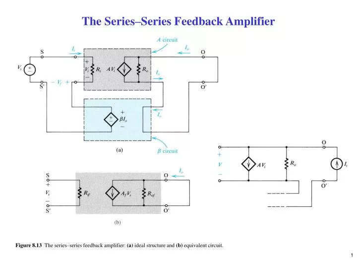
The Series–Series Feedback Amplifier. Figure 8.13 The series–series feedback amplifier: (a) ideal structure and (b) equivalent circuit. The Practical Case.

E N D
The Series–Series Feedback Amplifier Figure 8.13 The series–series feedback amplifier: (a) ideal structure and (b) equivalent circuit.
The Practical Case Figure 8.15 Derivation of the A circuit and the b circuit for series–series feedback amplifiers. (a) A series–series feedback amplifier. (b) The circuit of (a) with the feedback network represented by its z parameters. (c) A redrawing of the circuit in (b) with z21 neglected.
Figure 8.16 Finding the A circuit and b for the voltage-mixing current-sampling (series–series) case.
The Shunt–Shunt Feedback Amplifier Figure 8.19 Block diagram for a practical shunt–shunt feedback amplifier.
Figure 8.20 Finding the A circuit and b for the current-mixing voltage-sampling (shunt–shunt) feedback amplifier in Fig. 8.19.
The Shunt–Series Feedback Amplifier Figure 8.23 Block diagram for a practical shunt–series feedback amplifier.
Figure 8.24 Finding the A circuit and b for the current-mixing current-sampling (shunt–series) feedback amplifier of Fig. 8.23.
An Alternative Approach for Finding Ab Figure 8.26 A conceptual feedback loop is broken at XX¢ and a test voltage Vt is applied. The impedance Zt is equal to that previously seen looking to the left of XX¢. The loop gain Ab = –Vr/Vt, where Vr is the returned voltage. As an alternative, Ab can be determined by finding the open-circuit transfer function Toc, as in (c), and the short-circuit transfer function Tsc, as in (d), and combining them as indicated.
Figure 8.27 The loop gain of the feedback loop in (a) is determined in (b) and (c).