3D CONSTRAINED LEAST-SQUARES KIRCHHOFF PRESTACK TIME MIGRATION
520 likes | 991 Views
3D CONSTRAINED LEAST-SQUARES KIRCHHOFF PRESTACK TIME MIGRATION. Alejandro Cabrales Vargas. OUTLINE. MOTIVATION WHAT CLSM CAN DO WHAT CLSM CANNOT DO IMPLEMENTATION OF CLSM NUMERICAL EXAMPLES: RESULTS IN 2D NUMERICAL EXAMPLES: PRELIMINAR RESULTS IN 3D TO DO CONCLUSIONS AKNOWLEGEMENTS.

3D CONSTRAINED LEAST-SQUARES KIRCHHOFF PRESTACK TIME MIGRATION
E N D
Presentation Transcript
3D CONSTRAINED LEAST-SQUARES KIRCHHOFF PRESTACK TIME MIGRATION Alejandro Cabrales Vargas
OUTLINE • MOTIVATION • WHAT CLSM CAN DO • WHAT CLSM CANNOT DO • IMPLEMENTATION OF CLSM • NUMERICAL EXAMPLES: RESULTS IN 2D • NUMERICAL EXAMPLES: PRELIMINAR RESULTS IN 3D • TO DO • CONCLUSIONS • AKNOWLEGEMENTS
MOTIVATION • Kirchhoff algorithm is an economical and extensively used technique to perform 3D prestack-time migration. • However, coarse sampled data generates acquisition footprint and aliasing artifacts, which seriously interfere with the interpretation of shallow targets. • They negatively affect prestack techniques like AVO and elastic inversion. • Irregular sampling makes difficult and ambiguous the velocity analysis. • Can constrained least-squares migration (CLSM) be used to reduce these artifacts and improve the seismic amplitudes?
MOTIVATION Here we can observe the impact of the acquisition footprint in seismic interpretation. Taken form Falconer and Marfurt (2008)
WHAT CLSM CAN DO • Reduce aliasing artifacts caused by coarse and/or irregular sampling in the acquisition geometry. • Improve seismic amplitudes in prestack migrated data (e.g. CIG), what makes AVO results more reliable. • Predict missing traces in the data. This allows a better velocity analysis, e.g. for depth migration. • Due to the flexibility in the choice of the constraint function, CLSM can be adapted to solving a specific problem.
WHAT CLSM CANNOT DO • Cannot predict unrecorded seismic events. • Cannot fix inaccuracies in the velocity field. The CLSM method assumes the velocities are correct. • Generally it cannot eliminate stretch (we still have to mute). • Cannot always improve the final migrated stack image. Stacking is a very powerful filter.
IMPLEMENTATION OF CLSM Theory relates seismic data to Earth’s reflectivity. We control the quality of the synthetic data! E.T. Salt model MODELING: d = Gm
IMPLEMENTATION OF CLSM We want to revert the process. But in real life, seismic data is not perfectly acquired… IRREGULAR ACQUISITION … so in the final migrated gathers, the image is severely affected! Common offset gather Common image gather MIGRATION: m’ ≈ GTd
IMPLEMENTATION OF CLSM But we may use constrained least-squares migration to interpolate missing traces… CLSM: PREDICT MISSING TRACES … and to improve the quality of the migrated gathers! Common offset gather Common image gather CLSM: [GTG]mlsq ≈ GTd
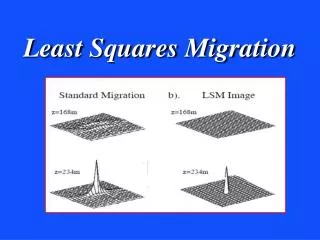
IMPLEMENTATION OF CLSM Final stack, conventional migration However, stacking attenuates the aliasing noise, so migrated stack images are very similar. Final stack, CLSM
2D WORKFLOW • I test conventional Kirchhoff migration and CLSM in the anisotropic version of Marmousi (Alkalifah, 1997) and in the Hess Corporation’s VTI datasets (available at the SEG software website). Nevertheless, I am not currently testing anisotropy. • I generate aliasing artifacts by killing about 2/3 of the traces in the datasets to simulate a severe 3D irregular acquisition. • I compare the original data with the predicted data obtained by conventional migration and CLSM. • I compare representative near-offset sections, common-image gathers (CIG) and the full stack sections after conventional migration and CLSM.
Common-shot gathers predicted with conventional migration MARMOUSI
Prestack Kirchhoff migration 3rd nearest offset MARMOUSI
Prestack CLSM (5 iter.) 3rd nearest offset 3rd nearest offset MARMOUSI
Prestack Kirchhoff migration 300th CIG MARMOUSI
Prestack CLSM (5 iter.) 300th CIG MARMOUSI
Prestack conventional migration Full stack MARMOUSI
Prestack CLSM (5 iter.) Full stack MARMOUSI
Common-shot gathers predicted with conventional migration HESS VTI
Prestack Kirchhoff migration HESS VTI 3rd nearest offset
Prestack CLSM (5 iter.) HESS VTI 3rd nearest offset
Prestack Kirchhoff migration 1500th CIG HESS VTI
Prestack CLSM (5 iter.) 1500th CIG HESS VTI
Prestack Kirchhoff migration HESS VTI Full stack
Prestack CLSM (5 iter.) HESS VTI Full stack
3D WORKFLOW • I tested conventional migration in the Dickman 3D data set. • I decimated the data in time (from 2 to 4 ms) and used every two input traces. I cropped the volume in time, using just the first 1.2 s. Decimation apparently enhanced acquisition footprint. • The 3D version of the CLSM algorithm still is in debugging.
Prestack Kirchhoff migration Full stack Crossline 60
Prestack Kirchhoff migration Full stack Inline 60
TO DO • Final minor debugging in 2D CLSM algorithm. • Major debugging in 3D CLSM algorithm. • Memory management in 3D CLSM (MPI parallelization). • Incorporation of SEP libraries in the codes (give up working with ASCII files!). • Optimization of the constraint function in 3D CLSM.
2D CONCLUSIONS • CLSM can reconstruct missing traces in an irregularly sampled dataset. • CLSM attenuates aliasing noise due to coarse sampling in CO sections and CIG. • Most aliasing noise is attenuated by stacking. Hence, CLSM and conventional Kirchhoff migration stacked sections are similar. • CLSM requires migration and modeling at each iteration, thereby increasing the cost. However, AVO, velocity analysis and other prestack processes can be greatly improved.
3D PRELIMINAR CONCLUSIONS • 3D Kirchhoff migration algorithm shows sensible performance when tested in the Dickman dataset. • Amplitude preservation has to be included in the code. • Acquisition footprint in the Dickman migrated volume constitutes the main challenge for the 3D CLSM algorithm!
AKNOWLEDGEMENTS • Thanks to Dr. Marfurt, Dr. Tim and Dr. Keller, my committee members. • Thanks to the Pemex E&P crew for their support (mainly economical!) • Thanks to quasi-Dr. Kui Zhang and quasi-Dr. Bo Zhang and all my friends. • Thanks to “Tio Sergio”, for being here and for many years of advice! • And of course, thanks for your attention!