Download

1 / 27
270 likes | 496 Views
Mechanical Engineering Department. DESIGN AND FABRICATION OF AN EXPERIMENTAL SETUP FOR SINGLE PLANE BALANCING. Project Members- Nithin Seenivasan Nandaganesh M.R.Chitthaarth. 8 th March, 2010 . Project Details. Introduction.

E N D
Mechanical Engineering Department DESIGN AND FABRICATION OF AN EXPERIMENTAL SETUP FOR SINGLE PLANE BALANCING Project Members- NithinSeenivasan Nandaganesh M.R.Chitthaarth 8th March, 2010
Introduction • This project involves design and fabrication of an experimental setup to help the mechanical engineering students to understand the concept of balancing of rotating masses (single plane balancing) by conducting an experiment in theDynamics Laboratory. • The system works in close tandem between theory and practical application.
Balancing and its Importance • Balancing of masses is a very critical and an important in rotating machineries of modern day industries • Unbalance refers to the center-of-gravity of the rotor being out of alignment with its center-of-rotation (eccentricity) • In most homes, looking around many rooms you can find air conditioners, CD or DVD player and the television • All of these consumer electronic products include internal rotating parts (motors), which if unbalanced, will generate vibration and noise during rotation
Theory There are two types of Imbalance- • Static Unbalance- The unbalance experienced when an object is static • Dynamic Unbalance- The unbalance experienced when an object is moving The experimental model will be based on Dynamic balancingof masses.
Dynamic Balancing • When a shaft rotates at an angular velocity ωrad/sec about a fixed axis, say the x-axis, and carries a body of mass m on a plane P with its centre of mass not lying on the x-axis, a centripetal force of mr ω 2 acts on the mass • This force, if not counter-balanced, leads to an imbalance called Dynamic Balancing • This effect is depicted in the diagram shown in the next slide
Model Components The following components are fabricated and assembled in our setup • An electric motor of 1/12 hp power • A rope drive system • A supporting frame • A shaft • A disc • Ball bearings • Eccentric masses
Component Dimensions The materials selection, cross sections, size of the components are calculated using strength based design approach and are listed as follows
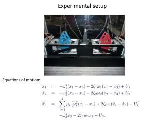
Experimental Setup • The experimental setup consists of a shaft, mounted on two bearings. • The shaft is a stepped type shaft, with a M24 thread of 1 mm pitch machined on 75 millimeters of the length. It is a solid mild Steel shaft. • The rest of the length is a plain machined type, with a 20 millimeters diameter. • The bearings used are nonshield type ball bearings, of 20 mm internal diameter and 42 mm external diameter and 11 millimeters thickness. • The disc is a 4 mm thick, also made of Mild Steel and a 23 millimeter hole is drilled in the center and a M24 internal thread is made on it, with a pitch of 1 millimeter. • 10 holes of 3 millimeters diameter, spaced at 10 millimeters each are made at every 45 degrees of the disc, amounting to 60 holes in the disc.
Fabrication Processes Used • Drilling (frame, disc, eccentric masses) • Welding (chain, disc and shaft) • Facing (disc) • Threading (disc, shaft)
Example Problem “Two masses A, B are placed on a balanced disc as shown in Fig.7.1, both at radii of 70 mm respectively. Both the masses are 100 grams at right angle to each other. Find the counter balance mass that must be added at a radius of 62 mm in order to balance the system “
Solution-Force Polygon Scale- 1 cm= .0023Kgm
Solution- Experimental Verification • The two 100 grams masses are fixed to the disc, at right angles to each other, at 70 mm from the disc center. • One mass is taken as reference and 150 grams mass, whose value is obtained by solving the sum, is placed at 225o to the reference mass. • The radius of the third mass is taken as 62 mm, which is also obtained from solving the sum. • The motor is then run using the accelerator and if the frame does not vibrate vigorously at moderate speeds, then the sum is solved accurately.
Problems Encountered during Fabrication • Threading on a 4 mm thickness disc • Facing a 300 mm dia disc, due to the unavailability of large size chuck • Dealing with the static imbalance in the disc, due to density gradient
Lessons Learnt • Various processes like drilling, turning, facing, cutting etc were put to practical use, which led to deeper understanding of their working and importance • To design a product from scratch- the various processes and nuances involved • Team work and communication • Industry standards and a thorough knowledge of the layout of Broadway’s industrial area, including fruitful contacts being made
Conclusion This model was constructed for conducting the Single Plane balancing experiment in the Dynamics Lab. By solving the sum given and experimentally proving the results by using the model, the students are able to prove their results practically. Hence, after demonstrating the working of the machine, the apparatus is now ready to use for the Dynamics of Machinery Laboratory.
Acknowledgements • Special thanks to our Project Supervisors Prof. M.Kumarand Prof. Dr. V.Jayakumar, for their wonderful guidance and help throughout project. • We are indebted to Mr. S. Murugan and Mr. P. Gajapathy(Workshop Assistants), who were so gracious in providing their valuable input and assistance during fabrication. • We also thank Mr. A. Balasubramaniam, of Balkan Electronics for his continued support and help throughout the project and for helping us to become better engineers.