Download
1 / 23
230 likes | 365 Views
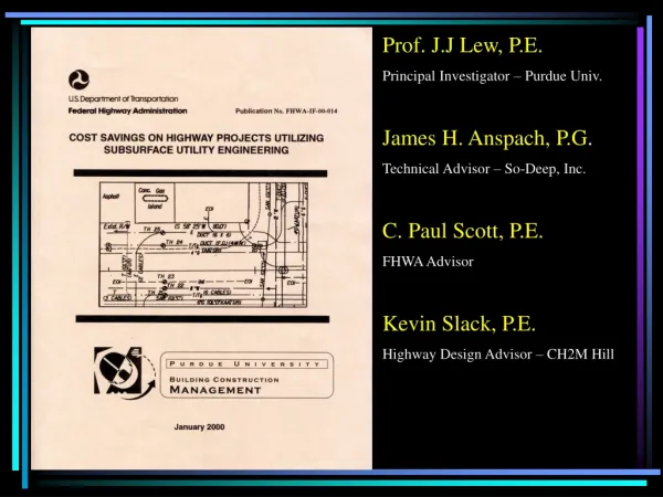
Completion of In-Situ Thermal Remediation of PAHs, PCP and Dioxins at a Former Wood Treatment Facility. Ralph S. Baker, Ph.D., John M. Bierschenk, P.G., James P. Galligan, P.E., and Ron Young TerraTherm, Inc., Fitchburg , Massachusetts, USA March 29, 2007. Sketch of ISTD Process.

E N D
Completion of In-Situ Thermal Remediation of PAHs, PCP and Dioxins at a Former Wood Treatment Facility Ralph S. Baker, Ph.D., John M. Bierschenk, P.G., James P. Galligan, P.E., and Ron Young TerraTherm, Inc., Fitchburg, Massachusetts, USA March 29, 2007
Sketch of ISTD Process • ISTD is the Simultaneous Application of: • Thermal Conduction Heating (TCH) • Vapor Recovery Treated vapor to atmosphere Vapor treatment Power Supply Knockout pot Heater and vacuum wells Heat exchanger Blower Power distribution system Pump Water treatment Discharge Temperature and pressure monitoring holes (1 of many) Treatment area foot-print
What Makes Thermal Conduction Heating (TCH) so Unique? • The Thermal Conductivity of a Wide Range of Soil Materials (gravel, sand, silt, clay) Varies Only by a Factor of ~3 • By Contrast: • Hydraulic / Pneumatic Conductivities Vary >106 – 108 • Electrical Conductivities Vary > 102 • TCH Heats the Entire Target Zone – No Locations are Bypassed or Unaffected • Soil Immediately Adjacent to TCH Wells Dries, Creating Permeability, Assisting Efficient Vapor Recovery • TCH Heaters Can Be Readily Controlled, to Achieve Low, Moderate or Higher Soil Temperatures as Needed
Heater-Vacuum Well Process Trailer Heater-Only Wells Heater- Vacuum Well Heater-Only Well Hexagonal Well Pattern ISTD Thermal Wells Heater- Vacuum Well . Thermal Destruction Zone
Typical Heating Progression for Various Levels of ISTD Treatment
Contrasting Applications of ISTD/TCH *For volumes > 1,500 m3, implemented in the U.S. **Thermally enhanced SVE, NAPL recovery, and bioremediation
CVOCs CVOCs TerraTherm, Inc. Shell TerraTherm Shell R&D 1980’s through 2000’s 1 21 22 2006 Chlorinated Benzenes, PAH, BTEX CVOCs 19 ISTD Development and Deployment 2005 20 CVOCs 18 CVOCs 17 MGP 16 PAHs, Dioxins 15 2004 CVOCs 14 11 2003 CVOCs/SVOCs, radionuclides 13 7 Chlorinated Pesticides 2 16 20 13 19 12 2002 Chlorinated Benzenes 9 8 11 10 PAHs 14 4 5 CVOCs 9 18 2001 12 3 15 21 22 17 2000 10 1999 1 PCBs 8 GRO/DRO, Benzene 7 PCBs Saipan 6 1998 CVOCs 4 PCBs 5 PCBs 3 ISTD Projects are also ongoing in Denmark and the U.K. 1997 PCBs 2 1996
Alhambra, California Site FeaturesFormer Wood Treatment Facility • Two Former Full-length Treatment Tanks (~3 x 21 x 1.7 m deep) • Two Former Butt-Dip Tanks (~3 x 14 x 4 m deep) • Former Boiler House and Tank Farm • Decommissioned Pipe Lines • Railroad Spurs
Piping Former Wood Treatment Tanks Former ASTs Former Boiler House • AOC-2 Treatment Area: • Heterogeneous fine silty sands • 2,800 m2 • 12,400 m3 • Avg. depth 6 m; max. depth 32 m • Water Table >82 m Former Railroad Spur
Soil Contaminant Concentrations and Cleanup Standards *Mean of 15 detects; PCP not detected in 231 samples B(a)P-Eq = Benzo(a)pyrene equivalents TEQ = 2,3,7,8-Tetrachlorodibenzodioxin Toxicity Equivalents
Alhambra ISTD Design Features • Target temperature (treatability results) of 335C (635F), maintained for 3 days • 2.1-m thermal well spacing • 785 thermal wells, total (131 heater-vacuum and 654 heater-only wells) • Insulated surface seal • Two treatment phases
Aerial View – December 2004 Phase 2 Phase 1
Thermal Well Fields Installed Phase 1 Phase 2
24/7 Continuous Manned Operation Monitoring Well Field Temperatures & Vacuum, Continuous Emissions Monitoring (CEM) of Off-Gas System Parameters Air Quality Control System Regenerative Thermal Oxidizer Air-to-Air Heat Exchanger Granular Activated Carbon Vessels Extraction Blowers CEM System Switchgear Electrical Transformer Inlet Manifold
Source Testing Results PCB Emission Limit: 2.44 g/dscm PCDD/PCDF Emission Limit: 2 x 10⁻⁴g/dscm
Compound MICR Phase 1 Phase 1 Phase 1 Phase 2 Limit Event 1 Event 2 Event 3 Event 1 3 3 3 3 3 ( µg/m ) ( µg/m ) ( µg/m ) ( µg/m ) ( µg/m ) Benzo(a)anthracene 23.9 0.869 0.610 1.00 0.946 Chrysene 239 1.27 1.34 1.83 2.89 Benzo(b)fluoranthene 23.9 0.341 0.172 0.898 0.686 Benzo(k)fluoranthene 23.9 0.149 0.0894 0.317 0.252 Benzo(a)pyrene 2.39 0.0954 0.0378 0.0839 0.1150 Indenopyrene 23.9 0.0793 0.0099 0.0681 0.0750 Dibenz(a,h)anthracene 6.74 0.0371 0.0069 0.0391 0.0400 Source Testing ResultsCarcinogenic PAHs MICR = maximum individual cancer risk
Well Field Layout and Representative Centroid Locations Phase 2 Centroid Phase 1 Centroid
Vaporization of Water Vaporization of Water Attainment of Attainment of Heater Circuits Shut Heater Circuits Shut Complete, Start of Complete, Start of Target Treatment Target Treatment Down, Start of Well Down, Start of Well Superheating Superheating Temperature Temperature Field Cool Field Cool - - Down Down Temperature °F Temperature °F 800 800 Target Treatment Target Treatment 700 700 Temperature 635°F Temperature 335°C 600 600 500 500 Description Description 400 400 T7A4B-4BHK19-4-8 T7A4B-4BHK19-4-8 300 300 200 200 100 100 0 0 2/9/2004 2/9/2004 7/1/2003 7/1/2003 8/7/2003 8/7/2003 11/6/2003 11/6/2003 12/2/2003 12/2/2003 1/14/2004 1/14/2004 6/11/2003 6/11/2003 7/20/2003 7/20/2003 8/26/2003 8/26/2003 4/17/2004 4/17/2004 10/11/2003 10/11/2003 12/28/2003 12/28/2003 7/1/2003 7/1/2003 8/7/2003 8/7/2003 2/9/2004 2/9/2004 3/4/2004 3/4/2004 6/11/2003 6/11/2003 7/20/2003 7/20/2003 8/26/2003 8/26/2003 11/6/2003 11/6/2003 12/2/2003 12/2/2003 1/14/2004 1/14/2004 4/17/2004 4/17/2004 3/4/2004 6:00 3/4/2004 6:00 10/11/2003 10/11/2003 12/28/2003 12/28/2003 Date Date Phase 1 Centroid Temperature °F
Temperature °F Temperature °F 900 900 Heater Circuits Heater Circuits Shut Down, Shut Down, 800 800 Start of Well Start of Well Field Cool Field Cool - - Target Treatment Target Treatment Down Down 700 700 Temperature 335°C Temperature 635°F 600 600 500 500 Attainment of Attainment of Description Description T11A2-2HG13-4-5 T11A2-2HG13-4-5 Target Target 400 400 Treatment Treatment Temperature Temperature 335°C 635°F 300 300 200 200 Vaporization of Water Vaporization of Water 100 100 Complete, Start of Complete, Start of Superheating Superheating 0 0 2/6/2005 2/6/2005 6/7/2005 6/7/2005 11/8/2004 11/8/2004 3/26/2005 3/26/2005 7/23/2005 7/23/2005 9/27/2005 9/27/2005 8/4/2004 8/4/2004 9/3/2004 9/3/2004 2/6/2005 2/6/2005 3/3/2005 3/3/2005 6/7/2005 6/7/2005 9/5/2005 9/5/2005 8/4/2004 6:00 8/4/2004 6:00 9/5/2005 0:01 9/5/2005 0:01 6/22/2004 6/22/2004 7/14/2004 7/14/2004 10/5/2004 10/5/2004 11/8/2004 11/8/2004 1/12/2005 1/12/2005 3/26/2005 3/26/2005 4/17/2005 4/17/2005 5/11/2005 5/11/2005 6/30/2005 6/30/2005 7/23/2005 7/23/2005 8/31/2005 8/31/2005 9/27/2005 9/27/2005 7/14/2004 8:00 7/14/2004 8:00 9/3/2004 16:00 9/3/2004 16:00 1/12/2005 8:00 1/12/2005 8:00 3/3/2005 14:00 3/3/2005 14:00 4/17/2005 8:00 4/17/2005 8:00 5/11/2005 6:30 5/11/2005 6:30 12/12/2004 12/12/2004 11/17/2005 11/17/2005 6/22/2004 18:00 6/22/2004 18:00 10/5/2004 14:30 10/5/2004 14:30 6/30/2005 16:00 6/30/2005 16:00 8/13/2005 14:30 8/13/2005 14:30 11/17/2005 7:00 11/17/2005 7:00 12/12/2004 22:30 12/12/2004 22:30 Date Date Phase 2 Centroid Temperature °F
Confirmatory sampling in well field Auger cuttings oxidation vs. pyrolysis ~2.7 m bgs ~0.3 m bgs ~5.5 m bgs Coke from product zone
Comparison of Pre- and Post-Treatment Contaminant Concentrations 30,600 Cleanup Goals 65 g/kg B(a)P 59 18 1g/kg Dioxin 0.11 N = 60 N = 47
Summary • Site demob. completed March 2006 • Estimated mass removed via combustion (oxidizer and subsurface) 395,000 kg (CO2 method) • Additional mass destroyed in situ by pyrolysis (dark soil/coke) • Air emissions were well below compliance requirements • Post–treatment soil sampling results all below stringent clean-up requirements • No Further Action letter (February 7, 2007) from California Department of Toxic Substances Control to Southern California Edison allows unrestricted land use
Cost Implications of Lessons Learned for Future Applications of ISTD at Creosote Sites • Achievement of unrestricted/residential land use by an in-situ remediation method is achievable and practical • ISTD was initially compared and selected over excavation with offsite incineration • ISTD remediation costs exceeded original estimates; however, all-in project cost was still ~40% lower than the excavation alternative • TerraTherm’s estimate for similar site of 12,600 m3, with one 130-day treatment is $500/m3: • Capital cost: $3.9M • Operations, source testing, and electricity: $2.2M • Demobilization, reporting, licensing fee: $0.23M