Download

1 / 67
670 likes | 826 Views
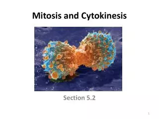
Cytokinesis following mitosis. Membrane Ruffling. ECIS Electric Cell-substrate Impedance Sensing. The basic principle of ECIS was first reported by Giaever and Keese, then at the General Electric Corporate Research and Development Center.

E N D
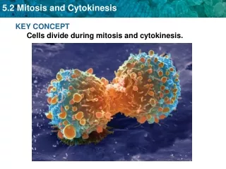
Cytokinesis following mitosis Membrane Ruffling
ECIS Electric Cell-substrate Impedance Sensing The basic principle of ECIS was first reported by Giaever and Keese, then at the General Electric Corporate Research and Development Center. Giaever, I. And Keese, C.R. PNAS 81, 3761-3764 (1984).
250 µm The ECIS Electrodes CE WE WE: Working Electrode CE: Counter Electrode
ECIS 8 well Array Array Holder in Incubator Space 250m
<1 A, 4000 Hz The measurement is non-invasive R C PC ECIS Electric Cell-substrate Impedance Sensing A cell morphology biosensor Culture medium (electrolyte) ECIS electrode Counter electrode AC Current source Phase sensitive impedance measurement PC
BSC-1cells NRK cells No cells Cell Inoculation (105 cells per cm2)
A published model fits the experimental data The measured impedance can be broken down into three parameters 1) Rb, the barrier function of the cell layer 2) Alpha, a term associated with the constricted current flow beneath the cell 3) Cm, the membrane capacitance [Giaever, I. and Keese, C.R., PNAS 81, 3761 (1991)]
What is measured using ECIS? Cell morphology changes including: 1) Barrier function of confluent layers 2) Relative size of cells and spaces beneath cells 3) Membrane capacitance All measurements are made in normal culture medium The measurement is non- invasive Limitations Cells must anchor and spread upon substratum A limited population of cells is measured at one time (1 to 1,000 cells)
COOH OOCCH3 Electric Cell-Substrate Impedance Sensing Viral Infection Ligand Binding Changes in Cell Morphology DNA RNA Metabolism Cytoskeleton Glucose Oxygen Physical Changes Shear, Electric Fields Drugs
Measurement of Metastatic Potential using ECIS™ BioTechniques, October 2002 Keese, Bhawe, Wegener and Giaever
The Dunning prostatic adenocarcinoma series was developed at Johns Hopkins and consists of several cell sublines. These all have their origin in a single line isolated from a prostatic tumor. After extensive passaging and mutagenesis, several distinct sublines were isolated having different in vivo metastatic abilities. Six of these lines were used in our studies.
Confluence verified To carry out the metastatic assay, first a layer of endothelial cells is established
Challenge of HUVEC cell layers with weakly (G) and highly metastatic (AT3) cell lines highly metastatic Challenge
Confluent HUVEC layer No cells MLL Challenge 105 cells/cm2
G Protein Coupled Receptor [Ca2+] Alterations in the cytoskeleton
CHO cells engineered to over-express the muscarinic receptor exposed to the agonist carbachol EC50 = ~1mM
The effect of carbachol is blocked by the antagonist pirenzipine (PZP)
Treatment of CHO-M1T cells with carbachol Data analysis using the ECIS model morphological information
Similar results are obtained with the beta adrenergic receptor
Adsorbed proteins alter cell spreading dynamics WI-38 VA/13 cells Electrodes were pre-coated with different layers of adsorbed protein before cell inoculation Cell inoculation 105 cells/cm2
Cell-free Capacitance at high freq. measures the open (cell-free) electrode area MDCK II cells inoculated on electrodes pre-coated with various proteins FN fibronectin LAM laminin VN vitronectin BSA bovine serum albumin FN BSA Confluent Inoculation
Adsorb BSA MDCK cells BSA is adsorbed to the electrodes and they are inoculated with MDCK cells after 24 hours remove cell re-inoculate with MDCK cells
Adsorb BSA MDCK cells after 24 hours remove cell re-inoculate with MDCK cells Laminin-like response
MDCK cells inoculated on fibronectin-coated electrodes with different concentrations of synthetic tetrapeptide RGDS present
MDCK cells inoculated on laminin-coated electrodes with different concentrations of synthetic tetrapeptide RGDS present
Elevated Field Applications 1 Electroporation 2 Wound healing assay
Elevated Field Applications 1 Electroporation 2 Wound healing assay
NORMAL MODE 1 MICROAMP, 10 MILLIVOLTS ELEVATED FIELD 1 MILLIAMP, A FEW VOLTS Elevated current applied ~200msec pore formation
Variation of the pulse duration: Lucifer yellow uptake Variation of the pulse duration: Lucifer yellow uptake MDCK Type II cells MDCK Type II cells Pulse: 40 kHz 4.0 V Pulse: 40 kHz 4.0 V 50 msec 100 msec 200 msec 500 msec
Uptake of dyes with different molecular weight Pulse: 40 kHz, 4.0 V, 200 msec Lucifer Yellow M = 0.5 kDa TRITC-dextran M = 76 kDa FITC-dextran M = 250 kDa Albany Medical College (F. Minnear) has demonstrated introduction of DNA constructs using the method and obtained expression of GFP
High field pulse for 100 msec Electroporation of bleomycin into HUVEC monolayers Electroporated control bleomycin only bleomycin with electroporation
Cell migration Traditional Wound Healing Assay Problems of reproducibility and quantification
Cell death Variation of the pulse duration: Lucifer yellow uptake MDCK Type II cells Pulse: 40 kHz 4.0 V 50 msec 100 msec 200 msec 500 msec
CELL WOUNDING NORMAL MODE 1 MICROAMP, 10 MILLIVOLTS ELEVATED FIELD 1 MILLIAMP, A FEW VOLTS Elevated current applied 15 seconds Severe pore formation localized heating
RPI Confluence Open electrode
NRK cells BSC-1 cells wounding