Download
1 / 40
400 likes | 483 Views
Instruction Set Architecture (ISA).

E N D
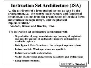
Instruction Set Architecture (ISA) “... the attributes of a [computing] system as seen by the programmer, i.e. the conceptual structure and functional behavior, as distinct from the organization of the data flows and controls the logic design, and the physical implementation.” – Amdahl, Blaaw, and Brooks, 1964. • The instruction set architecture is concerned with: • Organization of programmable storage (memory & registers): • Includes the amount of addressable memory and number of • available registers. • Data Types & Data Structures: Encodings & representations. • Instruction Set: What operations are specified. • Instruction formats and encoding. • Modes of addressing and accessing data items and instructions • Exceptional conditions.
Evolution of Instruction Sets Single Accumulator (EDSAC 1950) Accumulator + Index Registers (Manchester Mark I, IBM 700 series 1953) Separation of Programming Model from Implementation High-level Language Based Concept of a Family (B5000 1963) (IBM 360 1964) General Purpose Register Machines Load/Store Architecture Complex Instruction Sets (CDC 6600, Cray 1 1963-76) (Vax, Intel 432 1977-80) RISC (Mips,SPARC,HP-PA,IBM RS6000, . . .1987)
Types of Instruction Set ArchitecturesAccording To Operand Addressing Fields Memory-To-Memory Machines: • Operands obtained from memory and results stored back in memory by any instruction that requires operands. • No local CPU registers are used in the CPU datapath. • Include: • The 4 Address Machine. • The 3-address Machine. • The 2-address Machine. The 1-address (Accumulator) Machine: • A single local CPU special-purpose register (accumulator) is used as the source of one operand and as the result destination. The 0-address or Stack Machine: • A push-down stack is used in the CPU. General Purpose Register (GPR) Machines: • The CPU datapath contains several local general-purpose registers which can be used as operand sources and as result destinations. • A large number of possible addressing modes. • Load-Store or Register-To-Register Machines: GPR machines where only data movement instructions (loads, stores) can obtain operands from memory and store results to memory.
Code Sequence C = A + B for Four Instruction Sets Register Register Stack Accumulator (register-memory) (load-store) Push A Load A Load R1,A Load R1,A Push B Add B Add R1, B Load R2, B Add Store C Store C, R1 Add R3,R1, R2 Store C, R3
General-Purpose Register (GPR) Machines • Every machine designed after 1980 uses a load-store GPR architecture. • Registers, like any other storage form internal to the CPU, are faster than memory. • Registers are easier for a compiler to use. • GPR architectures are divided into several types depending on two factors: • Whether an ALU instruction has two or three operands. • How many of the operands in ALU instructions may be memory addresses.
ISA Examples Machine Number of General Architecture year Purpose Registers EDSAC IBM 701 CDC 6600 IBM 360 DEC PDP-11 DEC VAX Motorola 68000 MIPS SPARC 1 1 8 16 8 16 16 32 32 accumulator accumulator load-store register-memory register-memory register-memory memory-memory register-memory load-store load-store 1949 1953 1963 1964 1970 1977 1980 1985 1987
Examples of GPR Machines Number of Maximum number memory addresses of operands allowed SPARK, MIPS 0 3 PowerPC, ALPHA 1 2 Intel 80x86, Motorola 68000 2 2 VAX 3 3 VAX
Typical Memory Addressing Modes Addressing Sample Mode Instruction Meaning Register Immediate Displacement Indirect Indexed Absolute Memory indirect Autoincrement Autodecrement Scaled Add R4, R3 Add R4, #3 Add R4, 10 (R1) Add R4, (R1) Add R3, (R1 + R2) Add R1, (1001) Add R1, @ (R3) Add R1, (R2) + Add R1, - (R2) Add R1, 100 (R2) [R3] Regs [R4] ¬Regs[R4] + Regs[R3] Regs[R4] ¬Regs[R4] + 3 Regs[R4] ¬Regs[R4]+Mem[10+Regs[R1]] Regs[R4] ¬Regs[R4]+ Mem[Regs[R1]] Regs [R3] ¬Regs[R3]+Mem[Regs[R1]+Regs[R2]] Regs[R1] ¬Regs[R1] + Mem[1001] Regs[R1] ¬Regs[R1] + Mem[Mem[Regs[R3]]] Regs[R1] ¬Regs[R1] + Mem[Regs[R2]] Regs[R2] ¬Regs[R2] + d Regs [R2] ¬Regs[R2] -d Regs{R1] ¬Regs[Regs[R1] +Mem[Regs[R2]] Regs[R1] ¬Regs[R1] + Mem[100+Regs[R2]+Regs[R3]*d]
Addressing Modes Usage Example For 3 programs running on VAX ignoring direct register mode: Displacement 42% avg, 32% to 55% Immediate: 33% avg, 17% to 43% Register deferred (indirect): 13% avg, 3% to 24% Scaled: 7% avg, 0% to 16% Memory indirect: 3% avg, 1% to 6% Misc: 2% avg, 0% to 3% 75% displacement & immediate 88% displacement, immediate & register indirect. Observation: In addition Register direct, Displacement, Immediate, Register Indirect addressing modes are important. 75% 88%
Displacement Address Bits Needed Displacement Address Size Example Avg. of 5 SPECint92 programs v. avg. 5 SPECfp92 programs 1% of addresses > 16-bits 12 - 16 bits of displacement needed
Operation Types in The Instruction Set Operator TypeExamples Arithmetic and logical Integer arithmetic and logical operations: add, or Data transfer Loads-stores (move on machines with memory addressing) Control Branch, jump, procedure call, and return, traps. System Operating system call, virtual memory management instructions Floating point Floating point operations: add, multiply. Decimal Decimal add, decimal multiply, decimal to character conversion String String move, string compare, string search Graphics Pixel operations, compression/ decompression operations
instruction load 22% conditional branch 20% compare 16% store 12% add 8% and 6% sub 5% move register-register 4% call 1% return 1% Total 96% Instruction Usage Example: Top 10 Intel X86 Instructions Rank Integer Average Percent total executed 1 2 3 4 5 6 7 8 9 10 Observation: Simple instructions dominate instruction usage frequency.
Type and Size of Operands • Common operand types include (assuming a 32 bit CPU): Character (1 byte) Half word (16 bits) Word (32 bits) • IEEE standard 754: single-precision floating point (1 word), double-precision floating point (2 words). • For business applications, some architectures support a decimal format (packed decimal, or binary coded decimal, BCD).
Instruction Set Encoding Considerations affecting instruction set encoding: • To have as many registers and address modes as possible. • The Impact of of the size of the register and addressing mode fields on the average instruction size and on the average program. • To encode instructions into lengths that will be easy to handle in the implementation. On a minimum to be a multiple of bytes.
Three Examples of Instruction Set Encoding Operations & no of operands Address specifier 1 Address field 1 Address specifier n Address field n • Variable: VAX (1-53 bytes) Operation Address field 1 Address field 2 Address field3 Fixed: DLX, MIPS, PowerPC, SPARC Operation Address field Address Specifier Address Specifier 1 Address Specifier 2 Operation Address field Address Specifier Address field 2 Operation Address field 1 • Hybrid : IBM 360/370, Intel 80x86
Complex Instruction Set Computer (CISC) • Emphasizes doing more with each instruction • Motivated by the high cost of memory and hard disk capacity when original CISC architectures were proposed • When M6800 was introduced: 16K RAM = $500, 40M hard disk = $ 55, 000 • When MC68000 was introduced: 64K RAM = $200, 10M HD = $5,000 • Original CISC architectures evolved with faster more complex CPU designs but backward instruction set compatibility had to be maintained. • Wide variety of addressing modes: • 14 in MC68000, 25 in MC68020 • A number instruction modes for the location and number of operands: • The VAX has 0- through 3-address instructions. • Variable-length instruction encoding.
Example CISC ISA: Motorola 680X0 18 addressing modes: • Data register direct. • Address register direct. • Immediate. • Absolute short. • Absolute long. • Address register indirect. • Address register indirect with postincrement. • Address register indirect with predecrement. • Address register indirect with displacement. • Address register indirect with index (8-bit). • Address register indirect with index (base). • Memory inderect postindexed. • Memory indirect preindexed. • Program counter indirect with index (8-bit). • Program counter indirect with index (base). • Program counter indirect with displacement. • Program counter memory indirect postindexed. • Program counter memory indirect preindexed. Operand size: • Range from 1 to 32 bits, 1, 2, 4, 8, 10, or 16 bytes. Instruction Encoding: • Instructions are stored in 16-bit words. • the smallest instruction is 2- bytes (one word). • The longest instruction is 5 words (10 bytes) in length.
Example CISC ISA:Intel X86, 386/486/Pentium 12 addressing modes: • Register. • Immediate. • Direct. • Base. • Base + Displacement. • Index + Displacement. • Scaled Index + Displacement. • Based Index. • Based Scaled Index. • Based Index + Displacement. • Based Scaled Index + Displacement. • Relative. Operand sizes: • Can be 8, 16, 32, 48, 64, or 80 bits long. • Also supports string operations. Instruction Encoding: • The smallest instruction is one byte. • The longest instruction is 12 bytes long. • The first bytes generally contain the opcode, mode specifiers, and register fields. • The remainder bytes are for address displacement and immediate data.
Reduced Instruction Set Computer (RISC) • Focuses on reducing the number and complexity of instructions of the machine. • Reduced CPI. Goal: At least one instruction per clock cycle. • Designed with pipelining in mind. • Fixed-length instruction encoding. • Only load and store instructions access memory. • Simplified addressing modes. • Usually limited to immediate, register indirect, register displacement, indexed. • Delayed loads and branches. • Instruction pre-fetch and speculative execution. • Examples: MIPS, SPARC, PowerPC, Alpha
Example RISC ISA:PowerPC 8 addressing modes: • Register direct. • Immediate. • Register indirect. • Register indirect with immediate index (loads and stores). • Register indirect with register index (loads and stores). • Absolute (jumps). • Link register indirect (calls). • Count register indirect (branches). Operand sizes: • Four operand sizes: 1, 2, 4 or 8 bytes. Instruction Encoding: • Instruction set has 15 different formats with many minor variations. • All are 32 bits in length.
Example RISC ISA: HP Precision Architecture, HP-PA 7 addressing modes: • Register • Immediate • Base with displacement • Base with scaled index and displacement • Predecrement • Postincrement • PC-relative Operand sizes: • Five operand sizes ranging in powers of two from 1 to 16 bytes. Instruction Encoding: • Instruction set has 12 different formats. • All are 32 bits in length.
Example RISC ISA:SPARC 5 addressing modes: • Register indirect with immediate displacement. • Register inderect indexed by another register. • Register direct. • Immediate. • PC relative. Operand sizes: • Four operand sizes: 1, 2, 4 or 8 bytes. Instruction Encoding: • Instruction set has 3 basic instruction formats with 3 minor variations. • All are 32 bits in length.
Example RISC ISA: Compaq Alpha AXP 4 addressing modes: • Register direct. • Immediate. • Register indirect with displacement. • PC-relative. Operand sizes: • Four operand sizes: 1, 2, 4 or 8 bytes. Instruction Encoding: • Instruction set has 7 different formats. • All are 32 bits in length.
Registers R0 - R31 PC HI LO Instruction Encoding: 3 Instruction Formats, all 32 bits wide. OP rs rd sa funct rt OP rs immediate rt OP jump target RISC ISA Example: MIPS R3000 Instruction Categories: • Load/Store. • Computational. • Jump and Branch. • Floating Point (using coprocessor). • Memory Management. • Special. 4 Addressing Modes: • Base register + immediate offset (loads and stores). • Register direct (arithmetic). • Immedate (jumps). • PC relative (branches). Operand Sizes: • Memory accesses in any multiple between 1 and 8 bytes.
Register-Register 6 5 11 10 31 26 25 21 20 16 15 0 Op rs rt rd sa funct Register-Immediate 31 26 25 21 20 16 15 0 immediate Op rs rt Branch 31 26 25 21 20 16 15 0 displacement Op rs rt Jump / Call 31 26 25 0 target Op A RISC ISA Example: MIPS
Front-end per Language High-level Optimizations Global Optimizer Code generator The Role of Compilers The Structure of Recent Compilers: Dependencies Language dependent machine dependent Function: Transform Language to Common intermediate form Somewhat Language dependent largely machine independent For example procedure inlining and loop transformations Small language dependencies machine dependencies slight (e.g. register counts/types) Include global and local optimizations + register allocation Detailed instruction selection and machine-dependent optimizations; may include or be followed by assembler Highly machine dependent language independent
An Instruction Set Example: The DLX Architecture • A RISC-type instruction set architecture based on instruction set design considerations of chapter 2: • Use general-purpose registers with a load/store architecture to access memory. • Reduced number of addressing modes: displacement (offset size of 12 to 16 bits), immediate (8 to 16 bits), register deferred. • Data sizes: 8, 16, 32 bit integers and 64 bit IEEE 754 floating-point numbers. • Use fixed instruction encoding for performance and variable instruction encoding for code size. • 32, 32-bit general-purpose registers, R0, …., R31. R0 always has a value of zero. • Separate floating point registers: can be used as 32 single- precision registers, F0, F1 …., F31. Each odd-even pair can be used as a single 64-bit double-precision register: F0, F2, … F30
6 5 5 16 Opcode rs1 rd Immediate 6 5 5 5 11 Opcode rs1 rs2 rd func 6 26 Opcode Offset added to PC DLX Instruction Format I - type instruction Encodes: Loads and stores of bytes, words, half words. All immediates (rd ¬ rs1 op immediate) Conditional branch instructions (rs1 is register, rd unused) Jump register, jump and link register (rd = 0, rs = destination, immediate = 0) R - type instruction Register-register ALU operations: rd ¬ rs1 func rs2 Function encodes the data path operation: Add, Sub .. Read/write special registers and moves. J - Type instruction Jump and jump and link. Trap and return from exception
DLX Instructions: Load and Store LW R1, 30(R2) Load word Regs[R1] ¬32 Mem[30+Regs[R2]] LW R1, 1000(R0) Load word Regs[R1] ¬32 Mem[1000+0] LB R1, 40(R3) Load byte Regs[R1] ¬32 (Mem[40+Regs[R3]]0)24 ## Mem[40+Regs[R3]] LBU R1, 40(R3) Load byte unsigned Regs[R1] ¬32 024 ## Mem[40+Regs[R3]] LH R1, 40(R3) Load half word Regs[R1] ¬32 (Mem[40+Regs[R3]]0)16 ## Mem[40 + Regs[R3] ] # # Mem [41+Regs[R3]] LF F0, 50(R3) Load float Regs[F0] ¬32 Mem[50+Regs[R3]] LD F0, 50(R2) Load double Regs[F0] # # Regs[F1] ¬64 Mem[50+Regs[R2]] SW 500(R4), R3 Store word Mem [500+Regs[R4]] ¬32 Reg[R3] SF 40(R3) , F0 Store float Mem [40, Regs[R3]] ¬32 Regs[F0] SD 4 (R3), F0 Store double Mem[40+Regs[R3]] ¬-32 Regs[F0]; Mem[44+Regs[R3] ¬32 Regs[F1] SH 502(R2), R3 Store half Mem[502+Regs[R2]] ¬16 Regs[R3]16…31 SB 41(R3), R2 Store byte Mem[41 + Regs[R3]] ¬8 Regs[R2] 24…31
DLX Instructions: Arithmetic/Logical ADD R1, R2, R3 Add Regs[R1] ¬ Regs[R2] + Regs[R3] ADDI R1, R2, #3 Add immediate Regs[R1] ¬ Regs[R2] + 3 LHI R1, #42 Load high immediate Regs[R1] ¬ 42 ## 016 SLLI R1, R2, #5 Shift left logical immediate Regs[R1] ¬ Regs [R2] <<5 SLT R1, R2, R3 Set less than if (regs[R2] < Regs[R3] ) Regs [R1] ¬ 1 else Regs[R1] ¬ 0
DLX Instructions: Control-Flow J name Jump PC ¬ name; ((PC+4) - 225) £ name < ((PC + 4)+225) JAL name Jump and link Regs[31] ¬ PC+4; PC ¬ name; ((PC+4)- 225) £ name < ((PC + 4) + 225) JALR R2 Jump and link register Regs[R31] ¬ PC+4; PC ¬ Regs[R2] JR R3 Jump register PC ¬ Regs[R3] BEQZ R4, name Branch equal zero if (Regs[R4] ==0) PC ¬ name; ((PC+4) -215) £ name < ((PC+4) + 215 BNEZ R4, Name Branch not equal zero if (Regs[R4] != 0) PC ¬ name ((PC+4) - 215) £ name < ((PC +4) + 215
Sample DLX Instruction Distribution Using SPECint92
DLX Instruction Distribution Using SPECfp92