PDPWA Spectrometer
70 likes | 211 Views
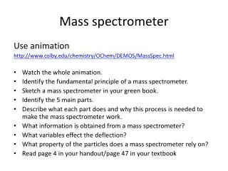
PDPWA Spectrometer. Simon Jolly 15 th June 2012. Spectrometer Specifications. Wakefield accelerated electrons ejected colinear with proton beam: need to separate the 2 and measure energy of electron beam only.

PDPWA Spectrometer
E N D
Presentation Transcript
PDPWA Spectrometer Simon Jolly 15th June 2012
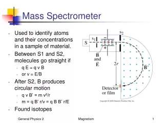
Spectrometer Specifications • Wakefield accelerated electrons ejected colinear with proton beam: need to separate the 2 and measure energy of electron beam only. • Must be able to resolve energy spread as well as energy: spectrometer must accept a range of energies, probably 0-2 GeV. • Simple conceptual layout: • Dipole mounted at plasma exit separates proton and electron beams. • Scintillator screen 4 m downstream of dipole intercepts electron beam ONLY. • Scintillator imaged by intensified CCD camera viewing upstream face of scintillator screen. Simon Jolly, University College London
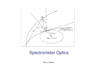
Spectrometer Layout Dipole separates protons from electrons AND puts energy-dependent spread in beam. Electrons intercepted by scintillator screen, imaged by high speed iCCD camera. Screen nominally 4 m from dipole. Dipole Electron beam Screen iCCD Camera Proton beam iCCD Image Low energy High energy Simon Jolly, University College London
Spectrometer Simulations • Beamline simulations to be carried out in General Particle Tracer to fix preliminary component layout. • Stage 1: • 2-D Gaussian beam, 0-2 GeV uniform energy spread, ideal dipole field. • Track beam from plasma exit 4 m downstream to screen. • Include proton beam: make sure we have good separation and adequate energy resolution. • Check effects of increasing drift or dipole field. • Stage 2: • Include “real” beam from plasma simulations. • Rerun particle tracking, optimising layout for best energy resolution. • Stage 3: • Measure field uniformity and fringe fields of real dipole magnet. • Include in particle tracking as field map: check effect of real fields on energy resolution. • Important: shorter dipole-to-screen distance means Dqdominates over x’ from beam. Disadvantage is more powerful dipole required: are there any others? Fringe fields? Simon Jolly, University College London
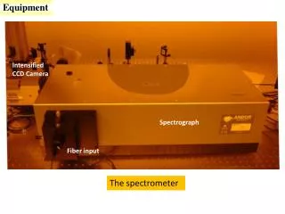
Spectrometer Camera • Camera already selected (funds approved within UCL). • Andor iStar 340T iCCD camera: • 2048 x 512 total pixels (1850 x 512 or 1330 x 512 active, depending on 18 mm or 25 mm intensifier). • 13.5 um pixels. • Gated intensifier <2 ns. • 16-bit readout, 150 ke- pixel full well. • http://www.andor.com/scientific_cameras/istar_iccd_camera/340-intensified-sensor/ • Camera setup: • DAQ and control software. • Data analysis software to give online measurement of witness beam energy spectrum. • Mechanical design of camera support system for tests and installation in SPS tunnel (comes later). Simon Jolly, University College London
340T Intensifier Options Gen 3 Intensifiers Gen 2 Intensifiers Simon Jolly, University College London
Questions for the Collaboration • What is the likely energy range of the witness beam? • Are there any preferred scintillators? Al2O3 (used in LHC)? YAG:Ce? Need: • High light output. • Radiation hard. • Vacuum safe. • What spectral range should the iCCD intensifier cover? Higher QE across only visible or broader range with lower QE? • What limitations are there on the geometry of the whole setup? Could we go to 10 m drift (for example) from dipole to screen rather than 4 m? • How close can we place camera to beamline? Closer means more light captured but greater chance of radiation damage… Simon Jolly, University College London