Download
1 / 49
490 likes | 514 Views
Learn the fundamentals of Orthographic Projections and 2-Dimensional Drawing in architecture. Explore how to visualize designs through plan, elevation, and section drawings before construction, ensuring accuracy and precision. Discover the difference between orthographic and isometric drawings and the importance of shapes in art and design.

E N D
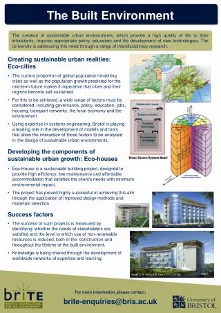
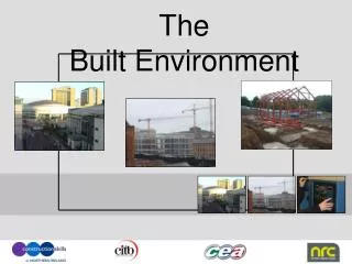
BUILT ENVIRONMENT COURSE • LESSON - (4)
LESSON - (4) Orthographic Projection Introduction Of Orthographic Projection & 2-Dimensional Drawing. B. Plan Drawing C. Elevation Drawing D. Section Drawing
ORTHOGRAPHIC PROJECTIONS Introduction to Orthographic Projections & 2-Dimension Drawing What is Orthographic Projectionmean? It means to represent three-dimensional objects in two dimensions. It is a form of projecting line parallel/perpendicular to a picture plane, resulting in every plane of the scene appearing in affined transformation on the viewing surface. The architect ultimately need the plan, elevation and sectional drawings to visualize the overall design, to considerate the height, proportionand other relevant factors, mathematically, to scale for the building, before construction. The process of such projection works on the plane is known as Orthographic Projection. For example ; An architect wish to design a building and he start to made the sketch of a perspective or isometric drawing/diagram, which is a form of 3-dimension drawings or picture, or perhaps we called it as an object and he need to project this object into a picture plane to further develop and establish a more elaborate design with windows, doors etc.
An orthographic drawing, sometimes also called a working drawing, is usually the last drawing produced by a designer. It normally has three accurate views of a product, a front view, side view and plan view. Dimensions (measurements) are also drawn on each view, ensuring the manufacturer can make the product to the precise size and the designers requirements. A parts list is also included. This has the precise measurements for every part of the product and includes details such as materials and finish. ORTHOGRAPHIC PROJECTIONS Fig.(B) – Orthographic Projection Diagram Fig. (A) - Orthographic Diagram after projection; Top, Front & Side View
What is the difference between orthographic drawing and isometric drawing? Fig.(D) – Orthographic Projection Diagram Orthographic is an 2D images of material or product which includes : Top View Front View Side Views Isometric is an 3D image of product. Side View Front View Fig.(C) - Showing the differences of Isometric & Orthographic Projection Plan View
ORTHOGRAPHIC PROJECTIONS Two-dimensional isometric or oblique views of a three-dimensional object on a drawing surface at right angles to the views and the lines of sight (projection). In these views the lines of the object parallel to the drawing surface are of true length and thus can be drawn to scale. Elevations, floor plans, and sections of a building are orthographic projections. Fig.(E) – Orthographic Projection of an Architecture Diagram
2-Dimensional Drawing What Does 2-Dimensional Mean? When a work of art is classified as being 2-dimensional, it means that the composition possesses the dimensions of length and width but does not possess depth (3- dimensional). All 2-dimensional pieces of art, such as drawings, paintings, and prints, are made up of shapes. 2-dimensional drawings are also when an areas known as shapes. Shapes are one of the building blocks of art and design. Shape Therefore, a shape is a 2-dimensional area that is defined in some way. It could be by a line, space, colour, texture or a variety of other ways. There are two types of shapes: geometric and free-form. Free form shapes are also referred to as organic. Some shapes are geometric. Geometric shapes are defined by name, through the contours that make up that shape. These shapes are classified by name like circle, square, rectangle, triangle, and so on. What makes geometric shapes unique is that their contours can be described mathematically.
Shapes that defy the classification of a geometric shape are considered to be free-form or organic shapes. Free-form shapes are generally irregular and uneven. One of the reasons free-form shapes are considered organic is because these types of shapes can be found in nature. Plant life, rock formations, clouds, animals, and the human body are all considered to be free-form shapes. Positive and Negative Shapes When looking at a 2-dimensional work, there are both positive and negative shapes that are incorporated into it. Apositive shape is usually defined as the figures or subject matter of a composition. A positive shape is explicitly defined by a line, colour, value, or texture. Anegative shape, however, is defined by space, or more accurately, what is known as negative space. Negative space is best thought of as empty space or a space that is not occupied by a defined object.
Example - A Two-dimensional Orthographic Geometric Projection Fig.(E.1 ) Fig.(E.2 ) Fig.(E.3)
Two-dimensional Free Form or Organic Orthographic Geometrical Projection Example – B Fig.(H.2) Fig.(H.1 ) Fig.(H.4) Fig.(H.3)
Example of the 2-Dimensional Drawings; Orthographic Geometric Projection – Architectural (Fig. L.3 & L.4) Example – C Fig.(L.3) Fig.(L.4)
Floor Plan What is Floor Plan and how it can be projected (orthographic Projection)? Afloor planis the most fundamental architectural diagram, a view from above showing the arrangement of spaces in building in the same way as a map, but showing the arrangement at a particular level of a building. Technically it is a horizontal section cut through a building (conventionally at 1.2m above floor level), The plan view includes anything that could be seen below that level: the floor, stairs (but only up to the plan level), fittings and sometimes furniture. Objects above the plan level (e.g. beams overhead) can be indicated as dashed lines. Geometrically, plan view is defined as a vertical orthographic projection of an object on to a horizontal plane, with the horizontal plane cutting through the building. Cutting horizontally across the building at 1.2m high. Reviewing the building components and internal space of the rooms or compartments. Reviewing the thickness of the walls, windows and doors are located, Reviewing other objects such as staircase, sanitary fitting and even fixture fitting etc. Include, reviewing floor finishes and the floor level.
Typical Architectural Working Drawing/Construction Layout Plan Fig.(PL-5)
When the project is complex and by putting every requirements into a single plan, may, looks complex and intimating sight for viewer. Therefore most of the cases, the floor plan is organize and superimpose to demarcate a specific layout plan for easier visual and prevent the congestion.
Various Type Of Layout Plan Or Floor Plan When The Project Size Is Large & Complex.
Architectural Working Drawing – Architect Plan Example – 1 Various Type Of Architectural Layout Plan – Partition & Floor Finishes Plan Fig.(PL-9) - Partition & Finishes Layout Plan
Architectural Working Drawing – Architect Plan Example – 2 Various Type Of Architectural Layout Plan; Electrical Fitting Layout Plan Fig.(PL-10) - Electrical Fitting Layout Plan
Architectural Working Drawing – Architect Plan Example – 3 Various Type Of Architectural Layout Plan; Furniture & Fixture Fitting Plan Fig.(PL-11) - Furniture &Door Schedule Layout Plan
Architectural Working Drawing – Architect Plan Example – 4 Various Type Of Architectural Reflected Ceiling Plan Fig.(PL-11) - Furniture &Door Schedule Layout Plan
Example – 5 Various Architectural Drawings Fig.(PL-12) For some case Enlarge Layout Plan is still required Fig.(PL-13) – Light-Fitting Layout Plan
Architectural Working Drawing – Architect Plan Example – 6 Various Type Of Architectural Layout Plan Fig.(PL-14) Lighting Layout Plan Fig.(PL-15) – Air-condition Layout Plan
Elevation Drawing What is Elevation and how it can be projected (orthographic Projection)? Elevations drawings can establish quickly by vertical projection from the plan with the same grid line setting. The height dimension is determine by certain minimum height and standard regulation height control by Authority or Governing Law for high rise building project at certain specific zone. Elevation show the building style and sizes. Elevation provide better visual of a building façade. It indicate all the doors and windows profile location & sizes. It show any other relevant components and finishes. It also reflect the pitch roof profile or flat roof. Ultimately it reflected the overall height of the building.
Architectural Working Drawing – Elevation Example – 7 Various Type Of Architectural Elevation - 1. Most of the Presentation -Elevation usually cast with shadow for visual impact. 2. Working Elevation –usually provide with more annotations and dimensions. Fig.(EL-2) – Working Elevation Fig.(EL-1) - Working Elevation
Architectural Working Drawing – Elevation Example – 7 Fig.(EL-3) – Presentation Elevation Fig.(EL-4) – Working Elevation
Section Drawing What is Section and how it can be projected (orthographic Projection)? Sectional drawing provide a cutaway view of a building to reveal what lays inside the building. Section reflect and reveal the internal structure. Section reveal the soffit of the ceiling. It show the fascial profile at the end corner of the building. It also reveal the floor thickness, beams and the columns expected sizes. It will also reveal the internal staircase or a void deck (mezzanine) if there is etc.
Section Drawing – Continue Across section, also simply called a section, represents a vertical plane cut through the object, in the same way as a floor plan is a horizontal section viewed from the top. In the section view, everything cut by the section plane is shown as a bold line, often with a solid fill to show objects that are cut through, and anything seen beyond generally shown in a thinner line. Sections are used to describe the relationship between different levels of a building. A sectional elevation is a combination of a cross section, with elevations of other parts of the building seen beyond the section plane There are usually at least two building section on the building. In some cases, additional section (or blown-up section) for particular view that cannot be determine from either the normal elevation or section drawings, is attach on the adjacent section
Architectural Working Drawing – Section Example – 8 Fig.(SE-5)
Example – 9 • Sectional View of High Rise Building Fig.(SE-1) – Conceptual Section Fig.(SE-2) – Schematic Section
Technical Drafting Symbols The drawing of an architectural working drawing requires a knowledge of the symbols and terms commonly used in the design and construction industry. All architectural workings must communicate in a clear and concise manner to the builder. Symbol are designed to approximately the appearance of an item, or the material. The symbol simplify the details on a drawing. It speed up the drawing time. Some symbols however, may have no graphic resemblance to the material or item that they are to represent. Therefore you may have to provide a legend with symbol and short description or annotation. This will clarify to the communication to builder. It must be remembered that architectural working drawings must be read by many persons in the building trades.
Example Of Symbol For Architecture Drawing Fig.(1) Fig.(2) RF-1 WF-1 Fig.(3) Fig.(4)
Fig. (SB-5 & SB-6) are Architectural Symbols for drawings. Example – 11 3000mm Dimensional Line Fig.(SB-6) Fig.(SB-5)
Example – 12 Example (12) – Living Set Furniture & Sanitary Symbol Fig.(SB-7 & SB-8) – Show the symbols of the furniture set & sanitary. Fig.(SB-8) Fig.(SB-7)
EXAMPLE-9 VARIOUS ARCHITECTURAL SYMBOLS Fig. (SB-1 & SB-2) are materials symbols for Surface and Sectional (Cut-away view) Fig.(SB-1) Fig.(SB-2)
EXAMPLE - 10 Fig. (SB-3) are materials symbols for Surface View and Floor Finishes Pattern Fig. (SB-4) are materials symbols for Surface and Sectional (Cut-away view) Fig.(SB-3) Fig.(SB-4)
ARCHITECTURE DRAWINGS - LEGEND LEGEND ARE CREATED WHEN THE PROJECT ARE LARGE AND COMPLEX TO REDUCE THE INTIMATE CONGGEST IN THE DRAWINGS.
LEGEND – PARTY WALL & FINISHES Example – 13
LEGEND – FIXTURE FITTINGS & DOOR SCHEDULE Example – 14
LEGEND – ELECTRICAL FITTING & AIR-CONDITIONING Example – 15