Download
1 / 45
480 likes | 528 Views
This seminar delves into techniques for luminosity measurement at the Large Hadron Collider (LHC) using cutting-edge methodologies. Explore the crucial role of luminosity data in high-energy physics experiments at ATLAS. Topics include total cross sections, beam properties, and precision requirements.

E N D
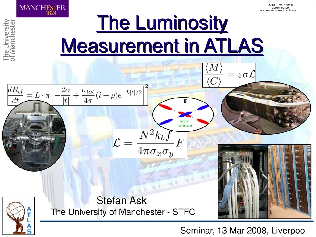
The Luminosity Measurement in ATLAS Stefan Ask The University of Manchester - STFC Seminar, 13 Mar 2008, Liverpool
Outline of the seminar • Luminosity and Methods • Reminder of the LHC luminosity • Main methods at pp colliders • Benefits/Requirements of the methods • ATLAS Strategy and Detectors • General strategy • LUCID (ATLAS Luminosity Monitor) • Alternatives for relative luminosity • Machine parameters • Physics processes • ALFA (ATLAS Absolute Luminosity) • The Full Measurement • Procedure and early uncertainties • Integration with ATLAS Stefan Ask (Luminosity in ATLAS) 13 Mar 2008, Liverpool
Luminosity: LHC Cross section = determined by physics process Luminosity = determined entirely by accelerator • Total Cross section () ~ 100mb • (Inelastic Cross section ~ 80mb) • Design Luminosity (L) ~ 1034 cm-2s-1 • ( = 107 mb-1 s-1) • Interaction Rate ~ 1 GHz But the beam is not continuous ! Stefan Ask (Luminosity in ATLAS) 13 Mar 2008, Liverpool
Luminosity: LHC Beam LHC Beam has a 40 MHz bunch structure (Only 2808 out of the 3564 BC will be filled due to injection etc.) Same bunch pair collides every time! Repeating 2808 individual bunch crossings (BC) • N = protons per bunch ~ 1.15 x 10¹¹ • kb = nr filled bunches ~ 2808 • Transverse beam dim. ~ 17 m • f = Revolution frequency • F = Correction from crossing angle • (see next slide) Stefan Ask (Luminosity in ATLAS) 13 Mar 2008, Liverpool
Luminosity: LHC Beam Due to the large number of bunches, the beams have to collide with a Crossing Angle Suppressing factor t ~ 17m At Design Luminosity, 1034cm-2s-1 Integrated luminosity per BC Mean nr interactions per BC (inelastic) Stefan Ask (Luminosity in ATLAS) 13 Mar 2008, Liverpool
Luminosity: Early Running First 3 Years of Running Despite that the luminosity is continuously increasing, significant pile-up can appear earlier than at 1033 cm-2s-1 (depending also on the number of bunches in the machine!) Stefan Ask (Luminosity in ATLAS) 13 Mar 2008, Liverpool
Luminosity: Importance Monitoring the Luminosity is of Large Importance for the Online Operation of the ATLAS Experiment • Fast information about running conditions • Study beam deterioration • Trigger optimization, e.g. pre-scale adjustments • Determine beam background • Prevent beam loss • Provide online luminosity measurement for LHC • Monitor luminosity bunch-by-bunch for potential offline use The relative precision is of main importance, e.g. to spot changes, Absolute precision can be moderate ( ~ 10%) Stefan Ask (Luminosity in ATLAS) 13 Mar 2008, Liverpool
Luminosity: Importance HBR • Importance for Analysis • Cross section for “Standard” processes • ttbar, W/Z etc. • New Physic evidence • Deviation from SM prediction • Higgs production study • Cross section • tanb in MSSM Higgs Luminosity dominating errors for many studies (even at 5%) Need as precise Absolute value as possible ATLAS Goal ~ 4-5% accuracy tan [ATLAS-TDR-15, May 1999] Stefan Ask (Luminosity in ATLAS) 13 Mar 2008, Liverpool
Methods: Different Colliders • e+e- or ep colliders normally determine luminosity from • An exclusive, well calculable process • with large cross section • and high efficiency and well defined acceptance • But pp colliders dominated by inclusive processes, • e.g. process + n Jets + beam remnant… • Hard to calculate precise cross section for processes • with large cross sections • Larger background contamination • Hard to define acceptance LEP ATLAS Luminosity measurement at pp colliders normally based on total (inelastic/elastic) cross section The precision of the luminosity measurement in ATLAS is determined by the systematic errors ! Stefan Ask (Luminosity in ATLAS) 13 Mar 2008, Liverpool
Methods: Collision (Zero) Counting Count the fraction of bunch crossings where any collision is observed nc = nr of observed colliding bunches nt = total number of bunches ( , mean nr of Interactions per bunch crossing • Benefits:Simple Detector ! • Only requires a detector which detect if any collision took place or not • Drawbacks:Non-linear ! • Saturates at high luminosity (when entering pile-up, i.e. > 1) • Measured quantity (nc/nt) must be measured for each BC pair separately • (in case of a non-uniform bunch structure) At high luminosity it is simpler to count the BC with no detected interaction. This is often called zero counting, nc/nt = 1 - nzero/nt Stefan Ask (Luminosity in ATLAS) 13 Mar 2008, Liverpool
Methods: Particle Counting Count the number of particles per bunch crossing M = nr of particles per (any) BC C = nr of particles per (detected) interaction measured at low luminosity, << 1, where only one interaction occur if any • Benefits:Linear ! • Linear with pile-up • Does not need individual bunch calculations • Drawbacks:More Advanced Detector ! • Requires particle counting capability More generally, this is a method of directly measuring the mean number of interactions per BC ( Stefan Ask (Luminosity in ATLAS) 13 Mar 2008, Liverpool
Methods: Absolute vs Relative Measured alone give the Relative luminosity Detection efficiency and cross section needed for Absolute scale Absolute calibration normally most difficult and give largest error contribution! Two main approaches Determine (calculate or measure) and separately Determine the luminosity from a dedicated absolute method under special (optimal) conditions in parallel with the Relative measurement Relative measurement has to be available always, e.g. for online diagnostics Absolute measurement should just be as precise as possible Stefan Ask (Luminosity in ATLAS) 13 Mar 2008, Liverpool
ATLAS Strategy and Detectors Stefan Ask (Luminosity in ATLAS) 13 Mar 2008, Liverpool
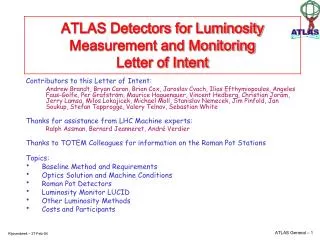
ATLAS Options • Use as many complementary methods as possible to get maximum • control of the systematics! • Including both dedicated and standard ATLAS detectors Relative Methods: • LUCID • Beam Condition Monitor • Min. Bias Scintillators • Tile / LAr Calorimeters • (ZDC - Heavy Ion runs) Absolute Methods: • LHC machine parameters • Well known physics processes (Z/W or mm/ee production) • ALFA (roman pot) detector (available from 2009) Dedicated (Final) Luminosity System Relative results can be refined offline also using complementary information, e.g. counting number of interactions using the ID (nr reconstructed vertices) Stefan Ask (Luminosity in ATLAS) 13 Mar 2008, Liverpool
Relative: LUCID(LUminosity measurement with a Cherenkov Integrating Detector) The dedicated (main) ATLAS Luminosity monitor Similar to the CLC detector at CDF The two LUCID modules Located at 17m on each side of the interaction point (IP) Stefan Ask (Luminosity in ATLAS) 13 Mar 2008, Liverpool
Relative: LUCID • 2 symmetric arrays of polished Aluminum tubes (Ø=1.5cm), filled with C4F10, • Surrounding the beam pipe and pointing at the IP (Z~17 m ) • Fit in available space and has low mass (< 25 kg/end) • Charged particles emit Cherenkov light at ~3 degrees • Photons propagate along the tube with multiple reflections (~2-3) and are read out by PMTs (Radiation hard) Stefan Ask (Luminosity in ATLAS) 13 Mar 2008, Liverpool
Relative: LUCID 4 tubes are readout by MaPMTs via fiber bundles (Test for high luminosity upgrade) PMT readout as bease line during low luminosity period • The PMT signal amplitude is used to count multiple particles in the same tube • The PMT time resolution allows to measure bunch-by-bunch luminosity • Upgrade with full coverage and using more radiation hard technology planned at the time of LHC upgrade for design luminosity Stefan Ask (Luminosity in ATLAS) 13 Mar 2008, Liverpool
Relative: LUCID LUCID should full fill all requirements for both collision and particle counting Baseline method from the start is particle counting, but multiple particle separation in the same tube should not be necessary until above 1033 cm-2s-1 (aka, hit counting) VJ Support Cone Hit Counting (No particle separation in the tube) LUCID Vessel Stefan Ask (Luminosity in ATLAS) 13 Mar 2008, Liverpool
38 cm 183cm Relative: MBTS and BCM Minimum Bias Trigger Scintillators Beam Condition Monitor • Diamond sensors • Suitable for both • particle and collision • counting • Small acceptance • Scintillator tiles on LAr Cryostat • Suitable for collision counting • Large acceptance • Will die when luminosity increase Stefan Ask (Luminosity in ATLAS) 13 Mar 2008, Liverpool
Relative: Tile / LAr Calorimeters The average energy in the calorimeters scale with the average nr. of minimum bias interactions per BC Tile LAr • Measured from: • LAr: Monitoring of HV in the LAr • Tile: Monitoring of the PMT currents Linear with pile-up! • Benefits and Drawbacks: • High precision • Normally outside ATLAS TDAQ system, can complicate association with a data set • (See later “full chain” slides) • Normally integrated over several BCs Valuable for relative luminosity online! Stefan Ask (Luminosity in ATLAS) 13 Mar 2008, Liverpool
Absolute: Machine Parameters Luminosity determined entirely by accelerator parameters Initial method for absolute calibration! Precision limited by: • Extrapolation of measurements of beam profiles elsewhere to IP (x, y), i.e. knowledge of optics, … • Precision in the measurement of the the bunch current (N2) • beam-beam effects at IP, effect of crossing angle at IP, … (Helmut Burkhardt) Stefan Ask (Luminosity in ATLAS) 13 Mar 2008, Liverpool
Absolute: Machine Parameters “Special Effort”: Calibrate the relative monitors of the experiments during dedicated runs with simplified LHC conditions (reduced intensity, fewer bunches, larger beam size…) These will optimize the condition for an accurate determination of both the beam sizes (overlap integral) and the bunch current. Requires dedicated LHC time! Expected precision relatively early = 10-20% Stefan Ask (Luminosity in ATLAS) 13 Mar 2008, Liverpool
Absolute: ee or Processes Intermediate method • Pure QED, cross section known to about 1% ! • Muons are back-to-back but with relatively low pT • Low rate, visible cross section ~ 1 pb • Low efficiency • (especially when pile-up cuts are necessary) Typical 1033 cm-2s-1 running: Luminosity MONITORING: 40 events per fill, Excluded Luminosity CALIBRATION: 1 % statistical error requires more than a year of running CDF result: First exclusive two-photon events observed in e+e-. …. but…. 16 events for 530 pb-1 for a σ of 1.7 pb overall efficiency 1.6 % Due to the well known cross section, a potentially very precise method But the statistics seems to be a strong limitation Stefan Ask (Luminosity in ATLAS) 13 Mar 2008, Liverpool
Absolute: W/Z Counting Intermediate method • Well known and large cross sections • Leptonic decays give clean signatures N = nr of W candidates Nbkg = nr of background events (uncertainties unknown before data) = efficiency for detecting W decay products (uncertainties from trigger eff. and lepton ID…) AW = acceptance of W decay products (theoretical uncertainty dominated by W polarization and PDFs, ~ 2 %) = theoretical inclusive cross section (uncertainties from partonic cross section, ~1%, and PDFs, ~5%) PDFs is the theoretical limitation Stefan Ask (Luminosity in ATLAS) 13 Mar 2008, Liverpool
Absolute: W/Z Counting The PDFs: At LHC the W/Z production will be dominated by sea-sea parton interactions at low-x The sea partons at Q2 ~ M2Z will be driven by the gluon, which is less precisely determined than the others HERA improved the PDFs dramatically! However, comparing different PDF sets still shows uncertainties up to 8% (worst case) for W/Z production at LHC Hope to constrain the PDFs further using early LHC data x = 5x10⁻⁴ to 5x10⁻² Expected (lum.) precision = 5-10% (constraining PDFs with early LHC data) Stefan Ask (Luminosity in ATLAS) 13 Mar 2008, Liverpool
Absolute: ALFA (Absolute Luminosity For ATLAS) Main absolute method Elastic scattering using detectors inside Roman Pots RP RP RP RP 240m IP 240m RP RP Elastic Scattering RP RP Stefan Ask (Luminosity in ATLAS) 13 Mar 2008, Liverpool
Absolute: ALFA 1) Coulomb Normalization: Inelastic Elastic EM Elastic Strong RP Coverage min = 2.7 rad max = 44.7 rad Central ATLAS limited Coverage 2) Optical Theorem: (traditional method) 3) Hybrid Solution: For example use optical theorem with total cross section measured by TOTEM… Stefan Ask (Luminosity in ATLAS) 13 Mar 2008, Liverpool
parallel-to-point focusing ydet y* y* Leff IP Absolute: ALFA Special Runs: Use parallel-to-point (large *) optics to reach very small scattering angles (or t-values) • Implications: • Low Luminosity, 1027 cm-2s-1 • Still need to be close to beam, • ymin = 1-2 mm IP Stefan Ask (Luminosity in ATLAS) 13 Mar 2008, Liverpool
Absolute: ALFA Roman Pot ALFA • Tracking Requirements: • x,y < 30 m • No significant (< 100 m) • non-active edge region • Operation at 40MHz • and in the Roman Pot Half~ 55 m Full~ 25 m All successfully demonstrated in test-beams! Stefan Ask (Luminosity in ATLAS) 13 Mar 2008, Liverpool
Absolute: ALFA • Measure luminosity from a fit to the • Reconstructed t-distribution • Using 10M events, corresponding to about • 100h of running at L=1027 cm-2s-1 • Edge located 1.5mm from the beam • No dead-edge-region and 30m resolution • Currently best estimate of systematic • uncertainties and background Fit to t, fit range 0.00055-0.055 Give an estimated precision of 2-3% ALFA Edge Stefan Ask (Luminosity in ATLAS) 13 Mar 2008, Liverpool
The Full Measurement Stefan Ask (Luminosity in ATLAS) 13 Mar 2008, Liverpool
Full Measurement Main Procedure: Run LUCID in parallel with calibration measurement (ALFA) Physics Run Luminosity • Initially, • LHC Machine Parameters • (Precision: ~10-20%) • Medium term • Physics processes,W/Z & /ee • (Precision: ~5-10%) • During 2009 • Roman Pot (ALFA) measurement • (Precision: ~2-3%) Calibrate LUCID Given by calibration Method (ALFA) Measured by LUCID Calibration Constant Stefan Ask (Luminosity in ATLAS) 13 Mar 2008, Liverpool
Full Measurement: Uncertainties LUCID Absolute (ALFA) • Main early uncertainties: • (Machine Par.) LHC + ATLAS perf. • (W/Z) Understand the data • (ALFA)Closest distance to the beam • (MC) “Physics related to tot“ • Potential non-linear effects • Saturation (hit counting) • Migration of secondaries • Coincidence effects • From non-uniform bunch structure • Background Many uncertainties are strongly dependent on the final LHC performance Simulations have not shown significant effects from non-linearity (especially for main studies of early data), but reality can of course surprise Will improve with time, e.g. from better beam quality and improvements from offline studies Stefan Ask (Luminosity in ATLAS) 13 Mar 2008, Liverpool
Full Measurement: Tevatron Experience CDF / CLC The CLC measurement at CDF could see many of the effects discussed • (Rel) Saturation from using hit counting • (no separation within a tube) • (Rel) Non-uniform bunch structure • (Abs) Dominating error came from • 1) Acceptance, MC geometry + generator • 2) Separate measurements of the total • cross section (CDF vs E811) Acceptance () Inelastic cross section () Other Stefan Ask (Luminosity in ATLAS) 13 Mar 2008, Liverpool
Full Measurement: Integration with ATLAS Integrated luminosity value relates to ALL events of a data sample during a SPECIFIC time period • Time synchronization between integrated luminosity and data samples will be done • by Luminosity Blocks (LB) which define a time interval of online running (few min) • Corrections of online luminosity wrt offline data (e.g. dead-time, pre-scales, …) • should be determined synchronously and be approximately constant during a LB • LBs are managed by the L1 trigger HW (Central Trigger Processor) • Only place in the ATLAS TDAQ where dead-time is introduced • Write LB number into both RoI data and Event Data to keep track down stream • For maximum control of online - offline corrections, the luminosity detectors should • be able to operate both inside and outside of the ATLAS TDAQ • (unlike luminosity determined from W/Z counting or Machine Parameters) • Data samples for analysis should contain an integer number of LBs • Integrated luminosity value for analysis will be retrieved from the conditions • database given a LB sequence Stefan Ask (Luminosity in ATLAS) 13 Mar 2008, Liverpool
Full Measurement: Luminosity Blocks Example, time intervals are synchronized by using Luminosity blocks Acceptance Time Interval Sum Over Valid dt Failures and Losses Instant. Luminosity Trigger Pre-Scale Efficiency TDAQ Live Time Luminosity Blocks (LB) quantify smallest time intervals of data taking Stefan Ask (Luminosity in ATLAS) 13 Mar 2008, Liverpool
Full Measurement: Corrections Luminosity (t) Analysis Event Sample (t) Corrections TDAQ ROD/ROS Event Loss Monitoring Dead-Time L1 Event File Access SFIs Pre-Scales L2 Pre-Scales Offline Processing EF Pre-Scales SFOs Multiple Streams Stefan Ask (Luminosity in ATLAS) 13 Mar 2008, Liverpool
Conclusions • The luminosity measurement at the LHC is inclusive and therefore sensitive to • systematics from variations of the conditions and hard to calculate precisely • It is of large importance and the error, normally dominated by the contribution from • absolute normalization, will be the limitation of many measurements • The dedicated luminosity system consists of the LUCID and ALFA detectors, but • several alternatives exist for early use and cross checks • LUCID (Rel): Cherenkov detector with aim to measure inelastic collisions • ALFA (Abs): Scintillating fiber tracker with aim to measure elastic pp scattering • Full measurement: Carry absolute calibration obtained at optimal conditions for • absolute method (low lum.) to conditions of physics runs (high lum.) • Controlling the corrections, needed to compare luminosity and offline data, • implies several technical requirements of the experiment • Much depends on the LHC performance, so it will be VERY exciting to see • the real conditions when LHC starts !! Stefan Ask (Luminosity in ATLAS) 13 Mar 2008, Liverpool
Back Up Slides ! Stefan Ask (Luminosity in ATLAS) 13 Mar 2008, Liverpool
Back Up: Bunch Shadowing Live-time, i.e. 1 - deadtime No BC correlation, e.g. dead-time introduced by backpreasure from DAQ BC correlated live-time, e.g. Non-uniform L distribution L1A introduce dead-time for the n following BCs High LB BCs introduce more dead-time to the following BCs Luminosity losses due to dead-time depend on LB of following BCs E.g. L L BCID BCID (L1A) (Dead-time) (L1A) (Dead-time) • Most likely a small effect (especially with few BCs), but must be understood • Requires: Luminosity with and independent of ATLAS TDAQ • Requires: Luminosity distribution over BCIDs Stefan Ask (Luminosity in ATLAS) 13 Mar 2008, Liverpool
Back Up: Non-Linear Collision Counting • Since in the collision counting method, LB and npp have • non-linear relation • Summing npp from all bunches is not equal to summing LB of all bunches High luminosity requires collision counting for the individual BCs (unless the bunch luminosities are identical) Stefan Ask (Luminosity in ATLAS) 13 Mar 2008, Liverpool
Back Up: Coincidence Paricle Counting LUCID with 200 tubes (No Secondaries) If necessary, due to halo Background Coincidence Side C Side A Any hit Non-linear Region • Small (large) , acceptance, • increase (decrease) non-linear • region Non-linear behavior known from Poisson statistics Can be corrected for (Single Diffractive) (Minimum Bias) (Double Diffractive) (Single Diffractive) Stefan Ask (Luminosity in ATLAS) 13 Mar 2008, Liverpool
Back Up: Saturation / Migraion Reminder: <M> = Mean nr particles (hits) per BC = inel x LB = Mean nr interactions per BC Saturation: No multi-particle separation within a tube give Saturation <M> • Addressed in full simulation • Estimated to be small Migration of Secondaries: Caused by secondary particles entering the tubes from the side Multiple particle add up to one hit. Pile-up give a non-linear component (not present for single interactions) <M> • Addressed in full simulation • Estimated to be small Stefan Ask (Luminosity in ATLAS) 13 Mar 2008, Liverpool
Back Up: MC Acceptance Example E.g. Badly described charged multiplicity in MC could give larger acceptance uncertainty for a small detector DD (low mult.) MB (high mult.) BCM 0.6% (7.5) 4.5% LUCID 41% ( 2 ) 85% Acceptance Large Detector Small Detector Multiplicity M Stefan Ask (Luminosity in ATLAS) 13 Mar 2008, Liverpool
Back Up: Common Analysis Values 10 fb-1 per year running at 1033 cm-2s-1: Assumption: Data taking 8 months per year at 50% efficiency -> 107 s -> 1033 cm-2s-1 = 106 mb-1s-1 = 10-6 fb-1s-1 -> 107 x 10-6 = 10 fb-1 per year at 1033 -> 100 fb-1 per year at 1034 Stefan Ask (Luminosity in ATLAS) 13 Mar 2008, Liverpool