Download
1 / 35
410 likes | 810 Views
Chapter 2. Microcontroller Architecture — PIC18F Family. Harvard Architecture. Von Neumann Architecture: Fetches instructions and data from a single memory space Limits operating bandwidth Harvard Architecture: Uses two separate memory spaces for program instructions and data

E N D
Chapter 2 Microcontroller Architecture— PIC18F Family
Harvard Architecture • Von Neumann Architecture: • Fetches instructions and data from a single memory space • Limits operating bandwidth • Harvard Architecture: • Uses two separate memory spaces for program instructions and data • Improved operating bandwidth • Allows for different bus widths
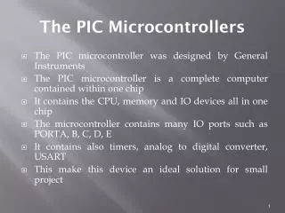
PIC18F Microcontroller Families • PIC microcontrollers are designed using the Harvard Architecture which includes: • Microprocessor unit (MPU) • Program memory for instructions • Data memory for data • I/O ports • Support devices such as timers
PIC18F – MCU and Memory 16 bit 2 MB 221 8 bit 4 KB 212
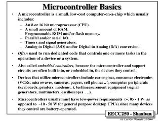
Microprocessor Unit (1 of 3) • Includes Arithmetic Logic Unit (ALU), Registers, and Control Unit • Arithmetic Logic Unit (ALU) • WREG – working register • Status register that stores flags • Instruction decoder – when the instruction is fetched it goes into the ID
Microprocessor Unit (2 of 3) • Registers • Bank Select Register (BSR) • 4-bit register used in direct addressing the data memory • File Select Registers (FSRs) • 16-bit registers used as memory pointers in indirect addressing data memory • Program Counter (PC) • 21-bit register that holds the program memory address while executing programs
Microprocessor Unit (3 of 3) • Control unit • Provides timing and control signals to various Read and Write operations
PIC18F - Address Buses • Address bus • 21-bit address bus for program memory addressing capacity: 2 MB of memory • 12-bit address bus for data memory addressing capacity: 4 KB of memory
Data Bus and Control Signals • Data bus • 16-bit instruction/data bus for program memory • 8-bit data bus for data memory • Control signals • Read and Write
PIC18F452/4520 Memory • Program Memory: 32 K • Address range: 000000 to 007FFFH • Data Memory: 4 K • Address range: 000 to FFFH • Data EEPROM • Not part of the data memory space • Addressed through special function registers http://www.microchip.com/ParamChartSearch/chart.aspx?branchID=1004&mid=10&lang=en&pageId=74
1 0 0 0 0 1 1 0 k k k k k k k k Instructions 8-bit Instruction on typical 8-bit MCU 8-bit Program Memory • Limits Bandwidth • Increases Memory Size Requirements • Example: Freescale ‘Load Accumulator A’: • 2 Program Memory Locations • 2 Instruction Cycles to Execute ldaa #k 16-bit Program Memory 16-bit Instruction on PIC18 8-bit MCU • Example: ‘Move Literal to Working Register’ • 1 Program Memory Location • 1 Instruction Cycle to Execute movlw k 0 0 0 0 1 1 1 0 k k k k k k k k • Separate busses allow different widths • 2k x 16 is roughly equivalent to 4k x 8
Program memory with addresses (Flash) Data memory with addresses PIC18F452/4520 Memory FFF=212=16x256=4096=4K
PIC18F452/4520 – Data Memory with Access Banks GPR=General Purpose Reg. SFR=Special Function Reg. These registers are always accessible regardless which bank is selected – acting as a virtual memory - FFF=212=16x256=4096=4K
Data Memory Organization PIC16F8F2520/4520 Register File Map 000h Access RAM 07Fh 080h Bank 0 GPR 0FFh 100h Bank 1 GPR • Data Memory up to 4k bytes • Divided into 256 byte banks • Half of bank 0 and half of bank 15 form a virtual bank that is accessible no matter which bank is selected 1FFh 200h Bank 2 GPR Access Bank 2FFh Access RAM 00h 7Fh Access SFR 80h FFh D00h Bank 13 GPR 256 Bytes DFFh E00h Bank 14 GPR EFFh F00h Bank 15 GPR F7Fh F80h Access SFR FFFh
PIC18F452 I/O Ports • Five I/O ports • PORT A through PORT E • Most I/O pins are multiplexed • Generally have eight I/O pins with a few exceptions • Addresses already assigned to these ports in the design stage • Each port is identified by its assigned SFR TRISB must be set to specify signal direction of PORT B.
Processes and Conditions of Data Transfer Parallel data transfer Serial data transfer MPU Initiating Unconditional Conditional (asks if device is ready) HW SW
MCU Support Devices (1 of 2) • Timers • Master Synchronous Serial Port (MSSP) • Addressable USART • A/D converter • Parallel Slave Port (PSP) • Capture, Compare and PWM (CCP Module)
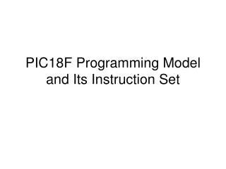
PIC18F Special Features • Sleep mode • Watchdog timer (WDT) • Code protection • In-circuit serial programming • In-circuit debugger
Questions - Table 2-9 (pp. 46 and 48) • How much of flash memory can be accessed? 13 bit 8K (1FFF) • Effective address bus fro data memory? 9 bit 512 Byte • How many instruction sets can be accessed? 35 – It has no multiplication!
PIC18F Instructions and Assembly Language • Has 77 instructions • Earlier PIC family of microcontrollers have either 33 or 35 instructions • In PIC18F instruction set, all instructions are 16-bit word length except four instructions that are 32-bit length
Instruction Description and Illustrations • Copy (Load) 8-bit number into W register • Mnemonics: MOVLW 8-bit • Binary format: 0000 1110 XXXX XXXX (any 8-bit number) • Copy Contents of W register in PORTC • Mnemonics: MOVWF PORTC, a • (‘a’ indicates that PORTC is in the Access Bank) • Binary format: 0000 1110 1000 0010 (82H is PORTC address) Opcode 8-bit Literal 8-bit Instruction
Instruction Set Overview Literal and Control Operations Literal Value 15 8 7 0 k k k k k k k k Opcode OR Opcode MOVLW 0 x 25 Literal Value
Illustration: Displaying a Byte at an I/O Port(1 of 5) • Problem statement: • Write instructions to light up alternate LEDs at PORTC. • Hardware: • PORTC • bidirectional (input or output) port; should be setup as output port for display • Logic 1 will turn on an LED in Figure 2.10.
Illustration (2 of 5) TRISC=0 • Interfacing LEDs to PORTC • Port C is F82H • Note that PORT C is set to be an output! • Hence, TRISC (address 94H) has to be set to 0
Illustration (3 of 5) • Program (software) • Logic 0 to TRISC sets up PORTC as an output port • Byte 55H turns on alternate LEDs • MOVLW 00 ;Load W register with 0 • MOVWF TRISC, 0 ;Set up PORTC as output • MOVLW 0x55 ;Byte 55H to turn on LEDS • MOVWF PORTC,0 ;Turn on LEDs • SLEEP ;Power down
PIC18 Simulator • Using the Program Memory editor type in the opcode MOVLW 00 and MOWWF TRISC,0 as described in page 52 of your textbook. • Run the program in step-by-step mode and observe the PC. • Observe how the NEXT INSTRUCTION changes. • What is the value of final clock cycle? • How long does it take to complete the program in sec.?
Example Memory content Hex code Mnemonics Memory content binary code Leave space
Illustration (4 of 5) • Execution of the instruction: MOVWF PORTC 1 Copy from WREGPORT C (82H) 2 1 2 Contains 55