Download
1 / 8
0 likes | 14 Views
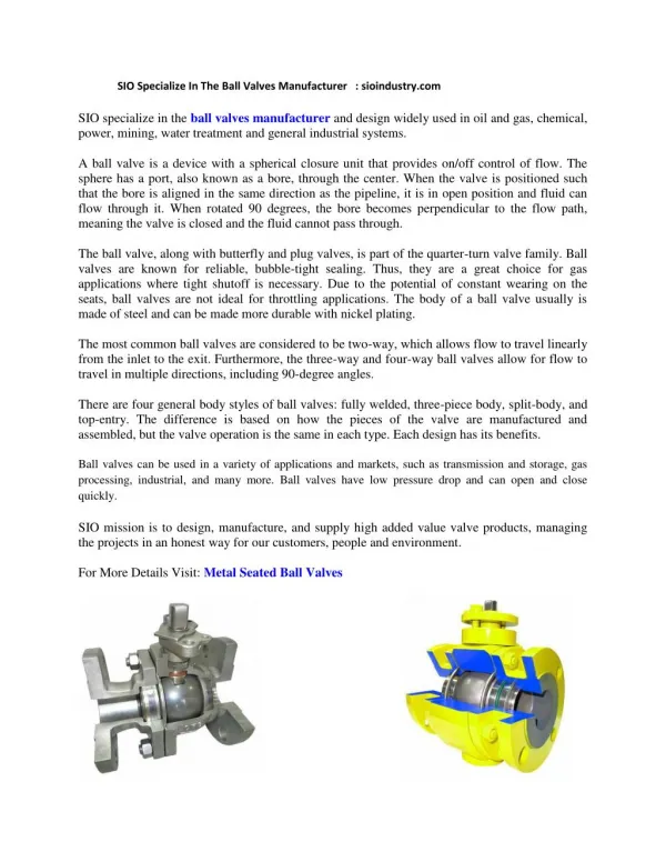
Manufacturer of Direct Mount Ball Valves with Blow out proof Stem feature which will prevent the stem from being pushed out due to the pressure inside the valve body. These Valves have a Direct Mounting Pad on top as per ISO 5211 to directly mount actuators on the valve without the use of any bracket coupler arrangement in between.

E N D
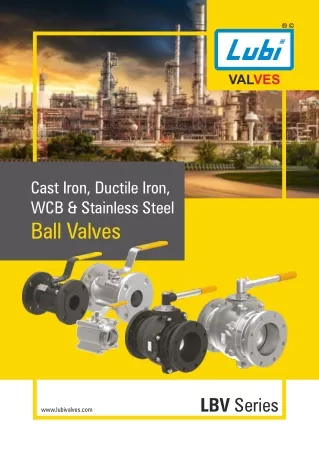
VALVES Cast Iron, Ductile Iron, WCB & Stainless Steel Ball Valves LBV Series www.lubivalves.com
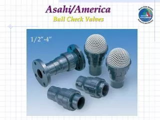
for HVAC INDUSTRIAL OIL & GAS WATER TREATMENT WASTEWATER PLANTS Ball Valves LBV Series Two Piece & Three Piece Class #150, #300 & #800
Standards Design Flange Details Face to Face Details Pressure Test ISO 17292 ASME B16.5 ASME B16.10 ISO5208 / API598 Material of Construction Two Piece / Three Piece Ball Valve WCB ASTM A216 Gr. WCB ASTM A351 Gr. CF8 AISI 304 AISI 304 M.S. Zinc Plated Part Name Body Ball Thrust washer Stem Stem Packing Body seal Collar Lock Nut Handle Seat Ring Studs with Nut Cast Iron ASTM A126 Gr. CI Stainless Steel ASTM A351 Gr. CF8 ASTM A351 Gr. CF8M ASTM A351 Gr. CF8M AISI 316 AISI 316 AISI 304 Virgin PTFE Virgin PTFE Virgin PTFE M.S. Zinc Plated Virgin PTFE M.S. Zinc Plated AISI 304 Torque Data in Nm Two Piece Test Pressure Maximum Working pressure Three Piece Size 15 20 25 40 50 Hydrostatic Shell Test Hydrostatic Seat Test Pneumatic Seat Test Class Size Class 150 25 40 50 65 80 100 150 200 Pressure - Temperature Chart for Seat Materials Class 300 14 40 46 98 165 185 350 - Class 150 4.5 5 8 26 32 10 28 34 46 124 130 250 650 5.5 bar (80 psi) 30 bar (435 psi) 22 bar (319 psi) 20 bar (290 psi) 150 77 bar (1116 psi) 5.5 bar (80 psi) 56 bar (812 psi) 51 bar (739 psi) 300 "PTFE" 76 bar (1102 psi) 5.5 bar (80 psi) 204 bar (2958 psi) 136 bar (1972 psi) 800 "RPTFE" 84 bar (1218 psi) Flanged Valves with PTFE seat Material Flanged Valves with RPTFE seat Material 60 60 PTFE 300# RPTFE 300# PTFE 150# RPTFE 150# 50 50 Pressure (bar) 40 40 Pressure (bar) 30 30 20 10 20 0 10 -30 -5 20 45 70 95 120 145 170 195 220 Temperature (°C) 0 -30 -5 20 45 70 Temperature (°C) 95 120 145 170 195 220 Threaded Valves with PTFE and RPTFE seat Material 80 RPTFE PTFE 70 60 Pressure (bar) 50 40 30 20 10 0 -30 -5 20 45 70 Temperature (°C) 95 120 145 170 195 220
TWO PIECE BALL VALVE Design Features Handle Stem Lock Nut Collar Thrust washer Seat Packing Body seal Ball Body Seat Ring • Blowout Proof SS Stem. • Removable Handle. • Lockable in Full open & Closed Position. • Actuator Mounting Pad. • CED coated body in CI & WCB Series.
Design Features THREE PIECE BALL VALVE Handle Collar Stem Body Seal Stem Packing Seat Ring Thrust washer Ball Body • PTFE seats with low pressure back seal. • Mirror Finished SS Ball. • Anti-Static Stem Design. • Fire safe seat feature. • Pressure Relieving Mechanism.
BALL VALVE Main Features • It is suitable where simple open/shut application is needed. • Flow Rate can also be controlled by partially opening or closing the valve to various degrees. • Our valves are designed to have minimal pressure drop & keep the flow rate high. • They are easy to operate as from full opening to full closing only needs a 90° rotation. • Valves are designed & manufactured with Blow out proof Stem feature which will prevent the stem from being pushed out due to the pressure inside the valve. • The stem is sealed with stem packing to prevent leakage & held in position by housing which is bolted into the valve body. • The two piece ball valve can be locked by a pad lock in full open or closed position. • We provide actuator mounting pad for easy automation as per standard ISO 5211 in two piece ball valve. • Our Balls have smooth mirror finish for tight sealing & obtaining lower operating torques. • We have designed our seats with fine slots which are used for relieving pressure and also helps to • prevent seat damage during closed position at high temperature. • All valves have Anti static feature as standard. • Our two piece valves have a Fire -Safe feature, which means that when the PTFE seat melts, the ball tightly butts with the metal seat which controls any leakage. Size / Dimensions TWO-PIECE FULL-BORE BALL VALVE (#150 & #300) SIZE / DIMENSIONS L #150 H Size DN 25 40 50 65 80 100 150 200 Size NPS 1 1-1/2 2 2-1/2 3 4 6 8 ØD Ød A #150 #300 125 156 165 191 210 254 318 - #300 165 190 216 241 282 305 403 - #150 #300 85 119 139.5 170 170 185 247 - 108 127 152 178 191 229 280 345 127 165 178 190 203 229 394 457 83.5 119 139.5 170 170 185 247 324 24 38 49 62 75 98 150 198 149 193 200 317 378.5 378.5 697 756 Note: All Dimensions are in mm unless mentioned otherwise.
Size / Dimensions THREE PIECE BALL VALVE THREE PIECE FULL-BORE BALL VALVE (#150) THREE PIECE REDUCE-BORE BALL VALVE (#150) SIZE / DIMENSIONS SIZE / DIMENSIONS Size DN 15 20 25 40 50 Size NPS 1/2 3/4 1 1-1/2 2 Size DN 25 40 50 65 80 100 Size NPS 1 1-1/2 2 2-1/2 3 4 ØD L Ød ØD L Ød ØB H A H A 88.9 98.6 108 127 152.4 108 117 127 165 178 81.5 81.5 87.2 113.2 123 14 17 25 38 49 156.3 156.3 152.2 195.6 195.6 108 127 152 180 191 229 127 165 178 186.5 203 229 83.5 108 113 123 129 142 25 38 51 64 80 17 32 38 49 55 74 156 196 196 196 215 215 102.5 Note: All Dimensions are in mm unless mentioned otherwise. THREE PIECE SCREWED END BALL VALVE (#800) THREE PIECE SOCKET WELDED END BALL VALVE (#800) SIZE / DIMENSIONS ØD Size DN 15 20 25 40 50 Size NPS 1/2 3/4 1 1-1/2 2 ØB L H A BSPT NPT 1/2” 3/4” 1” 1-1/2” 2” SW (ØDXE) Ø21.8X10 Ø27.2X13 Ø33.8X13 Ø48.6X13 Ø61.1X16 1/2” 3/4” 1” 1-1/2” 2” 14 17 25 38 49 75 75 92 114 132 54 54 62 76 87 131 131 145 180 181 Note: All Dimensions are in mm unless mentioned otherwise.
Ordering Key 025 F F WB S L 1 2 LBV Series Class Construction Ball Type S - Solid Ball H - Hollow Ball SIZE mm / in 015 -1/2" 020 - 3/4" 025 - 1" 040 - 1.1/2" 050 - 2" 065 - 2.5" 080 - 3" 100 - 4" 150 - 6" 200 - 8" 1 - 150# 2 - 300# 3 - 600# (DN 15) (DN 20) (DN 25) (DN 40) (DN 50) (DN 65) (DN 80) (DN100) (DN 150) (DN 200) LUBI Ball Valve Floating Type 2 - 2 Piece 3 - 3 Piece Bore Type F - Full Bore R - Reduce Bore End Connection F - Flanged End B - BSPT Thread N - NPT Thread S - Socket Weld Operator L - Lever P - Pneumatic Actuator E - Electric Actuator B - Bare Stem Body Material ** CI - Cast Iron DI - Ductile Iron WB - WCB C8 - CF8 CF - CF8M Note : **Other Materials are available on request. VALVES LUBI INDUSTRIES LLP Lubi Corporate Campus - Near Tragad Under Pass, S.P. Ring Road, Tragad, Ahmedabad - 382 421. Gujarat, India. Phone : +91 - 79 - 61700100, Fax No. :+91 - 79 - 61700399. Sales Enquiries: sales@lubivalves.com www.lubivalves.com Product Improvement is a continuous process at ‘LUBI’. The data given in this publication is therefore subject to revision. 00.01.230223.0222 Customer Care Number : 09824200800