Download
1 / 5
50 likes | 118 Views
Comparison of magnetic measurements for Nd2Fe14B and Sm2Co17 PM types. Analysis of computed vs. measured gradients and field quality. Conclusions and findings on magnetization module. Future measurements with Rotating Coils system planned.

E N D
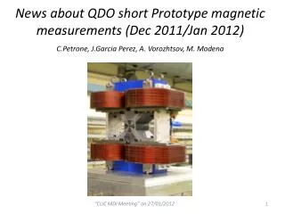
CLIC QD0 short prototype:Comparison of Magnetic Measurement for the two types of PM utilized C. Petrone, A. Vorozhtsov, M. Modena
Two campaign of measurements were done in 2012 with QD0 prototype in two different configuration:- in January 2012: the magnet equipped with the Nd2Fe14Bblocks was measured with the Vibrating wire system - in August 2012: the same type of measurement was done for the configuration with Sm2Co17 blocks . Here below are shown the measurements of the MEASURED Gradient (red dots) (extrapolated from the INTEGRATED GRADIENT effectively measured), together with the COMPUTED Gradient (blue curves). The measured Gradient in the configuration with Sm2Co17 blocks it is in very good agreement with the FEA computation. This is not the case for the Nd2Fe14B blocks were a difference of ~ - 6% is visible. This could have 2 possible explanation but the 1st was then excluded by a 2nd FEA cross-check: -The Permendur saturate at lower level than expected. The magnetization curve extracted from the Test Report of the raw material provided by the Supplier was utilized for the FEA computation that confirm that the problem is not coming by the Permendur quality. -The quality (magnetization module and/or direction) of the Nd2Fe14B PM blocks is not the expected one we should get more indication of this possibility when the PM blocks measuring device (by Helmholtz coils) will be delivery to the MM Section.
The curves below shows the INTEGRATED GRADIENT measured versus the QD0 powering (total coils current NI) for both QD0 configurations; upper graph for Nd2Fe14B, lower graph for Sm2Co17. To be noted that no demagnetization nor hysteresis effects are present (same gradient for same current all along the cycles)
The histograms provides for both QD0 configurations the magnetic harmonic content (multipoles) versus the magnet powering ; upper graph for Nd2Fe14B, lower graph for Sm2Co17. For comparison: the first computed “permitted” mutipole at NI=5000A is (integrated) : b6=1.4 units (with NdFeB) and b6=0.7 units (with SmCo).
(Preliminary) Conclusions: • The measured Gradient in the configuration with Sm2Co17 blocks is in very good agreement with the FEA computation. The configuration with Nd2Fe14B blocks shows a difference of ~ - 6% with the computed values. This effect is probably due to not correct magnetization (module and/or direction) of the Nd2Fe14B PM blocks. • The Field Quality shows that the measured permitted field components are well in agreement with the computation. The presence of all the other components (normal and skew not permitted) depends by errors in manufacturing of the Permendur part and in the magnetization module and/or direction of the PM blocks. (Anyway, for the sake of clarity, to not be forget that: • The accuracy of the MM wire system: > ± 4 units. • The field harmonics were measured at r=3 mm and than results SCALED to r=1 mm (radius at which field quality is specified). The scaling (that include also a 3D2D approximation), can introduce some errors. • The measured field harmonics are well inside the required tolerances (10 units) at the required (maximum) gradient. • The stability of the magnetic axis was confirmed inside ± 5μm all along the powering curve of the quadrupole. This is another important good results toward a real application of such compact FF quadrupole design. • The planned future measured with a dedicated Rotating Coils system should give more information and crosscheck of the magnet Field Quality. • Other measurements could be planned to better discriminate the contributions to the Field Quality of the quadrupolare structure in Permendure and of the PM blocks.