Download

1 / 26
260 likes | 320 Views
Announcements. mid-term Thursday (Oct 27 th ) Project ideas to me by Nov 1 st latest Assignment 4 due tomorrow (or now) Assignment 5 posted, due Friday Oct 21 st. Lecture 13 Overview. Active Filters Positive feedback Schmitt trigger/oscillator Analysing a more complex opamp circuit.

E N D
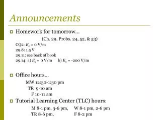
Announcements • mid-term Thursday (Oct 27th) • Project ideas to me by Nov 1st latest • Assignment 4 due tomorrow (or now) • Assignment 5 posted, due Friday Oct 21st
Lecture 13 Overview • Active Filters • Positive feedback • Schmitt trigger/oscillator • Analysing a more complex opamp circuit
Recap: Opamps • DC coupled, very high gain, differential amplifier. • Feed part of the output back into the inverting input to get stable operation in the linear amplification region • Golden rules under negative feedback: • The voltage at the inputs is the same (v+=v-) • No current flows into the opamp (i+=i-=0)
Active low-pass filter Max Amplification: RF/RS Low pass factor: 1/(1+ jωRFCF) Cut-off frequency (-3dB = 1/√2) when ωRFCF=1, ie ω0=1/RFCF e.g. RF/RS=10; 1/RFCF=1
Active high-pass filter Max Amplification: RF/RS High pass factor: 1/(1+ 1/jωRSCS) Cut-off frequency: ωRSCS=1 e.g. RF/RS=10; 1/RFCF=1
Active band-pass filter Combine the two: • Advantages of active filters: • no inductors (large, expensive, pick-up) • buffered (high input impedance, low output impedance) • – so filter performance independent of source and load; can cascade filters
Positive feedback • Consider what happens when there is a perturbation: • Negative feedback cancels out the difference between the inputs, providing stable amplification • Positive feedback drives opamp into saturation (at an exponential rate)
So what's the use of positive feedback?Comparator: Comparator compares two input voltages, vref and vsignal. if vsignal> vref the output voltage is high if vsignal< vref the output voltage is low Amplifier saturates when v+-v->10μV Simple version - no feedback Set v- = vref=0, input signal vsignal on v+:
vref Real world problem: noisy signal (inverted output) Small noise fluctuations generate spurious additional pulses before/after the main pulse
The Schmitt Trigger:Comparator with positive feedback in this state: Try R1=R2, VS=+/-15V in this state: • The circuit has 2 thresholds, depending on the output state • Gives a clean transition. • Known as hysteresis • Choose resistors to set required difference between the two voltage levels
Oscillator: We can create a clock v+=vo/2 v-=vC This sets the clock period ( RC) This sets the threshold levels vo sets the voltage at v+and charges the capacitor
What does this circuit do? • Break it down into elements
What does this circuit do? • Two buffers (voltage followers): vo=vi
What does this circuit do? • Inverting amplifier
What does this circuit do? X Y Z R • Voltage drop from point X to point Y = 2Vi , so: • Also, at point Z, VXZ
Now, gain • Multiply top and bottom by (1-jωRC): • None of the amplifiers change the amplitude:
What does this circuit do? R • The circuit is a phase shifter! • Output voltage is a phase shifted version of the input • Vary R to vary the degree of phase shift. Nice audio effect – but also… • Very useful for communications applications (e.g Electronically steerable microwave antenna arrays: PATRIOT= "Phased Array TRack to Intercept Of Target" )
What does this circuit do? • The circuit is a phase shifter! • Output voltage is a phase shifted version of the input • Vary R to vary the degree of phase shift • Very useful for communications applications (e.g Electronically steerable microwave antenna arrays: PATRIOT= "Phased Array TRack to Intercept Of Target" )
Non-Ideal Opamps: Basic Cautions • 1) Avoid Saturation • Voltage limits: VS-< vOUT < VS+ • In the saturation state, Golden Rules of opamp are not valid
Basic Cautions for opamp circuits • 2) Feedback must be negative (inverting) for linear behaviour • 3) There must always be negative feedback at DC (i.e. when ω=0). • Otherwise any small DC offset will send the opamp into saturation • Recall the integrator: In practice, a high-resistance resistor should be added in parallel with the capacitor to ensure feedback under DC, when the capacitive impedance is high 4) Don't exceed the maximum differential voltage limit on the inputs: this can destroy the opamp
Frequency response limits • An ideal opamp has open-loop (no feedback) gain A= • More realistically, it is typically ~105-106 at DC, dropping to 1 at a frequency, fT=1-10 MHz • Above the roll-off point, the opamp acts like a low-pass filter - and introduces a 90º phase shift between input and output • At higher frequencies, as the open-loop gain approaches 1, the phase shift increases • If it reaches >180º degrees, and the open loop gain is >1, this results in positive feedback and high frequency oscillations • The term "phase margin" refers to the difference between the phase shift at the frequency where the gain=1 (fT) and 180º
Frequency response limits • Open loop cut-off frequency, f0 (also known as open loop bandwidth) is usually small (typically 100Hz) to ensure that the gain is <1 at a phase shift of 180º • Closed-loop gain (gain of amplifier with feedback) begins dropping when open loop gain approaches RF/RS (in the case of the inverting amp) • Cut off frequency will be higher for lower closed-loop gain circuits Inverting amplifier
Slew rate (or rise time) • The maximum rate of change of the output of an opamp is known as the slew rate (in units of V/s) square wave input • The slew rate affects all signals - not just square waves • For example, at high enough frequencies, a sine wave input is converted to a triangular wave output due to limited slew rate
Slew rate example • Consider an inverting amplifier, gain=10, built using an opamp with a slew rate of S0=1V/μs. • Input a sinusoid with an amplitude of Vi=1V and a frequency, ω. • For a sinusoid, the slew rate limit is of the form AViω<S0. • We can therefore avoid this non-linear behaviour by • decreasing the frequency (ω) • lowering the Amplifier gain (A) • lower the input signal amplitude (Vi) • Typical values: 741C: 0.5V/μs, LF356: 50V/ μs, LH0063C: 6000V/ μs,