Download

1 / 15
150 likes | 583 Views
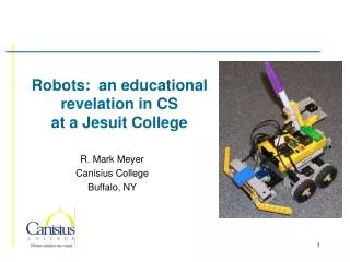
Final Demonstration: Dead Reckoning System for Mobile Robots. Lee Fithian Steven Parkinson Ajay Joseph Saba Rizvi. Problem Statement. Dead reckoning is navigation based on measurements of distance traveled from a known point.

E N D
Final Demonstration:Dead Reckoning System for Mobile Robots Lee Fithian Steven Parkinson Ajay Joseph Saba Rizvi
Problem Statement • Dead reckoning is navigation based on measurements of distance traveled from a known point. • Use a mobile robot and develop a synthesized dead reckoning navigation algorithm. • We will integrate various sensors.
Robot and Sensors • MARK III Robot with OOPic Chip • MEMS Accelerometer • MEMS Gyroscope • Shaft Encoders • Digital Compass
Algorithms We Tested • North Bound using Compass • Turning using Gyroscope • Turning using Encoders • Turning using Compass • Encoder x,y Movement
Algorithms We Tested (Cont) • Accelerometer x,y Movement • One-Direction using Accelerometer and Encoders • Turning using Encoders and Gyroscope • X, Y Path integrating sensors • Z Path using all sensors
Merging Data • Accelerometer and Encoders data merged for translations • Gyroscope and Encoders data merged for rotations • Weights found for each sensor by calculating percent errors
Merging Data (Cont) • Weights • Gyroscope - Rotational • CW – .11 • CCW – .19 • Accelerometer - Translational • .12 • Encoder • Rotational • CW – .89 • CCW – .81 • Translational • .88
Merging Data (Cont) • Equation • (Sensor1*weight1 + Sensor2*weight2) / Target < 1
DEMO 1:North Bound Using Compass • Robot will turn and travel towards north where ever it is initially pointing
DEMO 2: Z-Path integrating sensors • Uses combination of all sensors • Fusion of sensors ORANGE – gyroscope turns 90 degrees, CW RED – accelerometer travels 56 cm BLUE – encoder turns 150 degrees, CCW GREEN – encoder travels 64 cm BLACK – gyroscope and encoder merged to turn 150 degrees, CW PURPLE – accelerometer and encoder merged to travel 56 cm
Problems With Each Sensor • Accelerometer - Converting values - Unable to use Digital signal • Encoder - Mounting on Robot in an aesthetic manner • Gyroscope - Analog signal sensitive to noise - Converting values • Compass - Accuracy is very dependent on environment
Other Problems • Batteries change results • Unable to get PAK to work • Unable to use floating point
Refinements • Forty pin OOPic connecter • Pad per hole PCB • Five pin encoder connecter • Socket for accelerometer • Used analog mode for accelerometer • Software
Conclusion • Construction • Mark III based robot with shaft encoders, accelerometers, compass, gyroscope • Validation to ensure systems work at a basic level • Experimentation • Use dead reckoning navigation in trials. • Analysis • Numerical analysis of accuracy of navigation method.
Deliverables • Project Proposal • Implementation Notes • User’s Manual • Course Debrief • Notebooks • Robot • CD containing all files