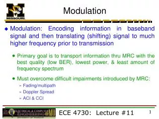
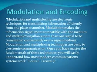
Carriers and Modulation
Carriers and Modulation. CS442. DIGITAL TRANSMISSION OF DIGITAL DATA. Review…. Baseband Transmission .

Carriers and Modulation
E N D
Presentation Transcript
Carriers and Modulation CS442
Baseband Transmission Digital transmission is the transmission of electrical pulses. Digital information is binary in nature in that it has only two possible states 1 or 0. Sequences of bits encode data (e.g., text characters). Digital signals are commonly referred to as baseband signals. In order to successfully send and receive a message, both the sender and receiver have to agree how often the sender can transmit data (data rate). Data rate often called bandwidth – but there is a different definition of bandwidth referring to the frequency range of a signal!
Baseband Transmission With unipolar signaling techniques, the voltage is always positive or negative (like a dc current). In bipolar signaling, the 1’s and 0’s vary from a plus voltage to a minus voltage (like an ac current). In general, bipolar signaling experiences fewer errors than unipolar signaling because the signals are more distinct.
Baseband Transmission Manchester encoding is a special type of unipolar signaling in which the signal is changed from a high to low (0) or low to high (1) in the middle of the signal. • More reliable detection of transition rather than level • consider perhaps some constant amount of dc noise, transitions still detectable but dc component could throw off NRZ-L scheme • Transitions still detectable even if polarity reversed Manchester encoding is commonly used in local area networks (ethernet, token ring).
ANALOG TRANSMISSION OF DIGITAL DATA Analog Transmission occurs when the signal sent over the transmission media continuously varies from one state to another in a wave-like pattern. e.g. telephone networks, originally built for human speech rather than data. Advantage for long distance communications: much less attenuation for analog carrier than digital
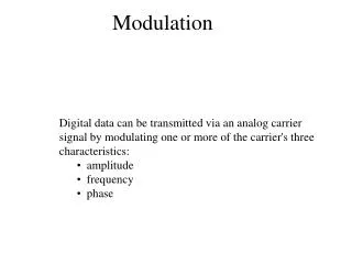
Digital Data to Analog Transmission Before we get further into Analog to Digital, we need to understand various characteristics of analog transmission.
Sine Wave • Peak Amplitude (A) • maximum strength of signal • volts • Frequency (f) • Rate of change of signal • Hertz (Hz) or cycles per second • Period = time for one repetition (T) • T = 1/f • Phase () • Relative position in time, from 0-2*pi • General Sine wave
Wavelength • Distance occupied by one cycle • Distance between two points of corresponding phase in two consecutive cycles • = Wavelength • Assuming signal velocity v • = vT • f = v • c = 3*108 ms-1 (speed of light in free space)
Frequency Domain Concepts • Signal usually made up of many frequencies • Components are sine (or cosine) waves • Can be shown (Fourier analysis) that any continuous signal is made up of component sine waves • Can plot frequency domain functions
Addition of FrequencyComponents Notes: 2nd freq a multiple of 1st 1st called fundamental freq Others called harmonics Period of combined = Period of the fundamental Fundamental = carrier freq
FrequencyDomain Discrete Freq Rep: Any continuous signal can be represented as the sum of sine waves! (May need an infinite number..) Discrete signals result in Continuous, Infinite Frequency Rep: s(t)=1 from –X/2 to X/2
Data Rate and Bandwidth • Any transmission system has a limited band of frequencies • This limits the data rate that can be carried • Spectrum • range of frequencies contained in signal • Absolute bandwidth • width of spectrum • Effective bandwidth • Often just bandwidth • Narrow band of frequencies containing most of the energy
Example of Data Rate/Bandwidth Want to transmit: Let’s say that f=1Mhz or 106 cycles/second, so T= 1microsecond Let’s approximate the square wave with a few sine waves:
Ex(1): Sine Wave 1 Bandwidth=5f-f =4f If f=1Mhz, then the bandwidth = 4Mhz T=1 microsecond; we can send two bits per microsecond so the data rate = 2 * 106 = 2Mbps
Ex(2): Sine Wave 1, Higher freq Bandwidth=5f-f =4f If f=2Mhz, then the bandwidth = 8Mhz T=0.5 microsecond; we can send two bits per 0.5 microseconds or 4 bits per microsecond, so the data rate = 4 * 106 = 4Mbps Double the bandwidth, double the data rate!
Ex(3): Sine Wave 2 Bandwidth=3f-f =2f If f=2Mhz, then the bandwidth = 4Mhz T=0.5 microsecond; we can send two bits per 0.5 microseconds or 4 bits per microsecond, so the data rate = 4 * 106 = 4Mbps Still possible to get 4Mbps with the “lower” bandwidth, but our receiver must be able to discriminate from more distortion!
Bandwidth / Representation 2000 bps B=500 Hz B=1000 Hz B=1700 Hz B=4000 Hz Increasing bandwidth improves the representation of the data signal. 500Hz too low to reproduce the signal. Want to maximize the capacity of the available bandwidth.
Multiplexers • A multiplexer puts two or more simultaneous transmissions on a single communications circuit. • Generally speaking, the multiplexed circuit must have the same capacity as the sum of the circuits it combines. • The primary benefit of multiplexing is to save money.
Multiplexing There are three major types of multiplexers • Frequency division multiplexers (FDM) • E.g. AM/FM Radio, Telephone • Time division multiplexers (TDM) • ISDN • Statistical time division multiplexers (STDM) • We’ll cover later (maybe) • Wavelength division multiplexing (WDM) • Used in optical carriers (colors carry signals)
Frequency Division Multiplexing (FDM) • Frequency division multiplexers can be described as dividing the circuit “horizontally” so that many signals can travel a single communication circuit simultaneously. • The circuit is divided into a series of separate channels, each transmitting on a different frequency. • Guardbands are employed to keep one channel from leaking over into another channel. • Frequency division multiplexers are somewhat inflexible because once you determine how many channels are required, it may be difficult to add more channels without purchasing an entirely new multiplexer.
Time Division Multiplexing (TDM) • Time division multiplexing shares a circuit among two or more terminals by having them take turns, dividing the circuit “vertically.” • Time on the circuit is allocated even when data are not transmitted, so that some capacity is wasted when a terminal is idle. • Time division multiplexing is generally more efficient and less expensive to maintain than frequency division multiplexing, because it does not need guardbands.
Transmission Impairments • Signal received may differ from signal transmitted • Analog - degradation of signal quality • Digital - bit errors • Caused by • Attenuation and attenuation distortion • Delay distortion • Noise
Attenuation • Signal strength falls off with distance • Depends on medium • Received signal strength: • must be enough to be detected • must be sufficiently higher than noise to be received without error • Attenuation is an increasing function of frequency; higher frequencies suffer from more attenuation. Can distort the signal. • Solution: Equalization. Boost higher frequency components.
Delay Distortion • Only in guided media • Propagation velocity varies with frequency • Velocity highest near center frequency • Results in phase shift at different frequencies • “Overlapping” bits • Solution: Equalization
Noise (1) • Additional signals inserted between transmitter and receiver • Thermal • Due to thermal agitation of electrons • Uniformly distributed • White noise • Intermodulation • Signals that are the sum and difference of original frequencies sharing a medium
Noise (2) • Crosstalk • A signal from one line is picked up by another • Impulse • Irregular pulses or spikes • e.g. External electromagnetic interference • Short duration • High amplitude
What Causes Errors? Summary of Errors and Noise: Source of Error What Causes It How to Prevent It. Line Outages White Noise Impulse Noise Cross-Talk Echo Attenuation Intermodulation Noise Jitter Harmonic Distortion Storms, Accidents Movement of electrons Sudden increases in electricity (e.g. lightning) Multiplexer guardbands too small, or wires too close together Poor connections Graduate decrease in signal over distance Signals from several circuits combine Analog signals change phase Amplifier changes phase Increase signal strength Shield or move the wires Increase the guardbands, or move or shield the wires Fix the connections, or tune equipment Use repeaters or amps Move or shield the wires Tune equipment Tune equipment
Error Prevention There are many ways to prevent errors: • Shielding (adding insulation) • Moving cables away from noise sources • Changing multiplexing type (FDMTDM) • Tuning transmission equipment and improving connection quality • Using amplifiers and repeaters • Equalization • Leasing conditioned circuits
Modulation - Digital Data, Analog Signal • Public telephone system • 300Hz to 3400Hz • Guardband from 0-300, 3400-4000Hz • Use modem (modulator-demodulator) • Amplitude shift keying (ASK) • Frequency shift keying (FSK) • Phase shift keying (PSK)
Amplitude Shift Keying • Values represented by different amplitudes of carrier • Usually, one amplitude is zero • i.e. presence and absence of carrier is used • Susceptible to sudden gain changes • Inefficient • Typically used up to 1200bps on voice grade lines • Used over optical fiber
Frequency Shift Keying • Values represented by different frequencies (near carrier) • Less susceptible to error than ASK • Typically used up to 1200bps on voice grade lines • High frequency radio • Even higher frequency on LANs using co-ax
FSK on Voice Grade Line Bell Systems 108 modem
Phase Shift Keying • Phase of carrier signal is shifted to represent data • Differential PSK • Phase shifted relative to previous transmission rather than some reference signal
Sending Multiple Bits Simultaneously Each of the three modulation techniques can be refined to send more than one bit at a time. It is possible to send two bits on one wave by defining four different amplitudes. This technique could be further refined to send three bits at the same time by defining 8 different amplitude levels or four bits by defining 16, etc. The same approach can be used for frequency and phase modulation.
Sending Multiple Bits Simultaneously In practice, the maximum number of bits that can be sent with any one of these techniques is about five bits. The solution is to combine modulation techniques. One popular technique is quadrature amplitude modulation (QAM) involves splitting the signal into eight different phases, and two different amplitude for a total of 16 different possible values, giving us lg(16) or 4 bits per value.
Sending Multiple Bits Simultaneously Trellis coded modulation (TCM) is an enhancement of QAM that combines phase modulation and amplitude modulation. The problem with high speed modulation techniques such as TCM is that they are more sensitive to imperfections in the communications circuit.