Modulation and Encoding
Modulation and Encoding.

Modulation and Encoding
E N D
Presentation Transcript
Modulation and Encoding “Modulation and multiplexing are electronic techniques for transmitting information efficiently from one place to another. Modulation makes the information signal more compatible with the medium, and multiplexing allows more than one signal to be transmitted concurrently over a signal medium. Modulation and multiplexing techniques are basic to electronic communication. Once you have master the fundamentals of these techniques, you will easily understand how most modern communications systems work.” Louis E. Frenzel Jr.
Modulation • Newton Telecom Dictionary: • The process of varying some characteristic of the electrical carrier wave as the information to be transmitted on that carrier wave varies • Text: “Modulation refers to the process of typically encoding digital data into analog signals for transmission. Page 143 • Modulation consists in superimposing the user or subscriber signal on a carrier signal (a constant tone), which is more adequate to the transmission medium. Modulation is the process of impressing information (voice, image, data, etc.) onto the carrier wave for transmission. ”
Modulation further defined • “Modulation is a signal-processing operation that is basic to the transmission of an information-bearing signal over a communication channel, whether in the context of digital or analog communications. This operation is accomplished by changing some parameter of a carrier wave in accordance with the information - bearing (message) signal. The carrier wave may take one of two basic forms, depending on the application...” • Sinusoidal carrier wave (amplitude, frequency, phase mod.) • Periodic sequence of pulses (amplitude, width, or position is modified – Introduction to Analog and Digital Comm. • By: Haykin, Moher
Encoding • Encoding: the process of converting data into code or analog voice into a digital signal. • With voice we need to covert it to a digital signal then multiplex it within the trunks for transmission. • With data we need to take it from it’s basic form and shape it in a way that we can send it from one location to the next. Ex. packets or RS232 communications.
Multiplexing • To transmit two or more signals over a single channel. • The channel may be wireless communications, wired or fiber based. • Baseband transmission takes up the entire channel or cable. • Example: a VCR feeds a signal to a TV. This is done either with a RF cable like RG 59U or with base band cables using RCA to RCA connectors for both video and audio. • CATV on the other hand uses a cable like RG6 to feed many channels at once. A much more efficient means of communicating! Now, think of multiple voice calls, multiple data streams, DTV, cellular calls....
Re-cap • Encoding • process of converting information into a digital code - analog voice into a digital signal for transmission • Modulation • This operation is accomplished by changing some parameter of a carrier wave in accordance with the information signal. • Purpose: to transmit the information over long distances • Multiplexing • transmit two or more signals over a single channel
Encoding the information • Taking an analog source signal level and creating a digital representation of that analog signal at a given point in time.
PCM Pulse Code Modulation • Uses a sampling technique to digitize analog signals. • Example: Telephone industry standard “Mu-Law” US and Japan. A-Law most other countries. (A-Law uses a companding technique that provides more quantizing steps at lower amplitude (volume) than at higher amplitude.) • Uses a sampling rate of 8000 times a second, an 8 bit digital equivalent reference is created and that is what is transmitted over the PSTN. • 8 Bits X 8000 = 64 Kbps digital stream.
Sampling of the information signal • Sample voltages are converted to a digital number • The number corresponds to the amplitude of the voltage at a given point in time • The digital number is then transmitted to the far end. • At the receive end the digital number is converted back to an analog signal • PCM – T1, T3 systems – first digital xmission of voice, 1957
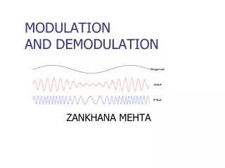
AM Amplitude Modulation • Basics of AM Mod/Demod • Concept of a carrier and information signal • Carrier for xmission • Information varies amplitude
FM Frequency Modulation • Information varies freq. • Phase Modulation • Information varies phase of carrier. • Play AM/FM simulation
Binary Phase Shift Keying • Alternative to FSK • A logic 1 results in positive • going signal at cycle start • A logic 0 results in negative • going signal at cycle start • Abrupt changes in BPSK signal • introduce bandwidth concerns
Pulse Amplitude Modulation • Pulse Amplitude Modulation • Samples of the analog input are made • The actual analog value of the signal at the sample time is used to represent signal information • Samples are taken at regular intervals • The pulse amplitude is either sent or used to modulate a carrier
Pulse modulation Circuit Clock reference Pulse Width Differentiated waveform Negative going Pulse phase Modulation
Pulse Width Modulation Input signal could be voice or some reference signal that comes from a sensor
Quadrature Phase Shift Keying • Bit pair 00 = 45 degree phase shift • Bit pair 01 = 135 degree phase shift • Bit pair 11 = 225 degree phase shift • Bit pair 10 = 315 degree phase shift • Notice the vectors have the same • amplitude • Bit pairs control the carrier phase angle • Each vector represents 2 bits of data rather than 1 as in BPSK • More information is transmitted per carrier phase angle
Truth table Constellation diagram
Encoding/Multiplexing • Space Division Multiplexing (SDM) • Examples • Time Division Multiplexing (TDM) • Example • Frequency Division Multiplexing (FDM) • Example • Spread Spectrum • Example
Space Division Multiplexing • It is like having six people in a room and lets say they all want to talk at the same time, there is going to be some interference between the conversations taking place. To reduce the interference set up three groups of two with as much separation between pairs as possible so each group will have a unique conversation. • Use multiple systems allows for multiple communication paths at the same time from any one point to another. • This is where individualdata streams are transmitted from different antennas simultaneously and received by different receivers. This creates multiple paths for information to be sent and can be achieved by using a limited frequency band. • Fiber • WDM Wave Division Multiplexing • DWDM Dense Wave Division Multiplexing • Riser cables
Time Division Multiplexing • Many input signals can be used to modulate the carrier – one at a time –TDM • This reduces the need for multiple modulator circuits • Added complexity in the multiplexer circuit • Since only one input has data sent at a time, the other inputs with data are not being sent at any given point in time • Analogy – old distributer caps on a vehicle
T-1 configuration 192 bits #1 #2 #24 8 bits 8 bits 8 bits 8 X 24 = 192 bits +1 synchronization bit (1 Frame) 193 bits per 1/8000 sec or 1.544 mbps
TDMA – Time Division Multiple Access used in Cellular phones
Frequency Division Multiplexing • AM Radio • FM Radio • TV broadcast • Home 2-way radios • CATV – PG151 Fig. 6-13 • Telephone Fig 6-14 • L1 systems in the 1930s had 600 voice channels • L5
ADSL-Asymmetric digital subscriber line • DSL is a dedicated line from the phone company to your home. This dedicated copper wire can carry far more data than the 3,000-hertz signal needed for your phone's voice channel. • If both the phone company's central office and your house are equipped with an ADSL modem on your line, then the section of copper wire between your house and the phone company can act as a purely digital high-speed transmission channel. • The phone line's bandwidth between 24,000 hertz and 1,100,000 hertz is divided into 4,000-hertz bands, and a virtual modem is assigned to each band. Each of these 249 virtual modems tests its band and does the best it can with the slice of bandwidth it is allocated. The aggregate of the 249 virtual modems is the total speed of the pipe.
Reading for next week • Chapter 7 Wireless Communications