Download

1 / 37
880 likes | 3.13k Views
FUEL OIL SYSTEM. www.powerpointpresentationon.blogspot.com. Light diesel oil (LDO) High speed diesel oil (HSD) Heavy Furnace oil (HFO) Low sulphur heavy stock (LSHS). Types Of Fuel Oil. LDO & HSD normally used in Auxiliary boiler Ignitor for certain boiler design.

E N D
FUEL OIL SYSTEM www.powerpointpresentationon.blogspot.com
Light diesel oil (LDO) High speed diesel oil (HSD) Heavy Furnace oil (HFO) Low sulphur heavy stock (LSHS) Types Of Fuel Oil
LDO & HSD normally used in Auxiliary boiler Ignitor for certain boiler design. HFO generally used for power boiler Use of different types
Heavy Fuel oil (HFO) specification: • service : Oil Burners • Standard: IS 1593/1971 Grade HV • Flash point(Min) : 66 deg,c • Viscosity (Maxm.) : 370 CST at 50 deg,c • Total sulphur : 4.5% by Weight • Gross Heating Value: 10270 Kcal/Kg Flash Point:The Flash point of a volatile liquid is the lowest Temperature at which it can vaporize to form a ignitable mixture In air.
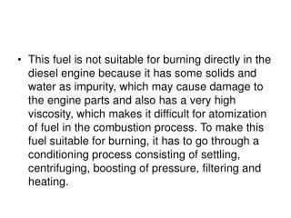
Fuel Oil: • Three Liquid Fuel used in power plant 1.Heavy Fuel Oil(HFO) 2.LSHS(Light sulphur Heavy stock) 3.HSD(High speed diesel) Oil firing is preceded by: 1.Lowering viscosity and increasing flowability on heating for better combustion 2.Droplet formation on atomization 3.Combustion initiation by High energy spark ignition.
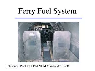
FUEL OIL SYSTEM: Purpose: • To establish initial Boiler Light up. • To support the Furnace flame during Low Load Operation FUEL OIL SYSTEM CONSISTS OF: • Unloading of fuel oil and storage system • Transfer of fuel oil to pressurising pump house • Drain oil system • Aux steam & condensate system • Electrical Tape tracing system: • Instrumentation & control system • Oil water separator system.
Heavy oil is received at the site in railway tankers of 20 tonne capacity each An unloading header with number of receiving points for number of wagons unloading is provided. The connections between loading header and tankers are through rubber flexible hosepipes. Railway tankers are equipped with steam heating coils. FO unloading system
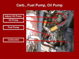
Strainers Transfer P/P
UNLOADING OF F.O AND STORAGE SYSTEM The Fuel oil is supplied by railway wagons. The installation has been Provided for unloading 76 wagons simultaneously.For this purpose one Number unloading header of size 400 NB have been laid between two Railway tracks with 84 nos. 80 NB branches with plug valves which Surve as unloading points.400 NB branch is taken from the unloading Header to the pump house which surves as the suction header for 5 nos. Unloading cum transfer pump.4 nos. pumps is used for unloading and I number as stand by.Each pump is 100 cm3 per hour capacity. At suction side of each pump simplex busket type strainer with 40 mesh Straining element is provided to make the oil free from foreign particles Which may cause damage to pump rotor. For storing the unloaded oils 3 nos. vertical cylinder,fixed roof vented Type storage tank of nominal capacity 2826 cum has been stalled.
2. TRANSFER SYSTEM: Oil from any of the 3 storage tanks can be transferred to the pressurising Pump house by gravity through 200 NB transfer header.It is also possibl To transfer oil from one storage tank to another , and for this purpose 200 Nb branch connection is taken from each section of transfer line of Each storage tank and a 350 NB common recirculation line is installed. Oil through this recirculation line would flow to suction header of un- Loading pumps and through the pump oil can be taken to any desired Storage tank by opening the desired inlet vv of storage tank.
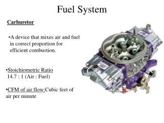
DRAIN OIL SYSTEM: In order to empty storage tank and or any branches, 80 NB and 25 NB ,Branch connection is taken from all lowest points and through a common Header of 80 NB connected to Drain oil tank of capacity 5 cum is Installed at lowest level of unloading pump house.Oil from drain oil Tank to storage tank is to be transferred by 4 cum/hr capacity ,Screw pump named Drain Pump thorugh 50 NB Drain Oil return header.
Drain Tank DRAIN HDR Oil Tank Drain Oil p/p
4. AUX STEAM & CONDENSATE SYSTEM: • Aux. Steam is being supplied from pressurising pump house area through 200 NB steam header.Steam is being received at a pressure of 16 kG/cm2 and 212 deg c. • Steam is drawn near each storage tank from the Aux steam header through 150 NB branch connection to supply steam to floor coil heater and suction heater. • Pressure reducing station is installed near unloading pump house to reduce the pressure of steam from 16 kg/cm2 to 4 kg/cm2. • Condensate from railway wagon is collected through steam trap station.For this purpose 42x2 nos steam trap stations have been installed along the railway tracks and 2 nos 100 Nb condensate header is provided along the oil unloading header. • 2 nos. condensate header is connected to 150 NB common condensate header which in turn connected to 5 cum capacity condensate flash tank. • Condensate from heaters are also taken to same flash tank and finally through 100 NB common header.
5. ELECTRICAL TAPE TRACING SYSTEM: To maintain the temp. of oil in the piping and equipment at desired oil Temperature,Electrical tracing tape is used.The tape used is constant Wattage type series resistance type of tape. The Oil temp. to be maintained is 65 deg c for HFO. 6. INSTRUMENTATION & CONTROL SYSTEM: Following instruments & controls have been provided : Pressure Indicator Differntial Pressure gauge Temperature Indicator Temperature switch
Return oil From Unit FILLING HDR Suction HDR Return Hdr I/L HEATER O/L Steam R/C
Steam to Atmosphere Return Steam From Heater Flash Tank Water to Sump Pit Sump Pump
Temperature control of oil through Floor coil heater: For controlling Temp oil in storage tank through floor coil control Valve (AS-CV_40-1,2,3) have been provided.Temperature in storage Tank is sensed through temperature switch(TS-4,5,6),which open or Close the solenoid valve as per predetermined temperature.(65 degc) set In temperature switch.When temp falls below 65 degc,solenoid vv open And instrument air from the instrument header flows through the Solenoid vv to actuators of control vv to close the vv. When temperature increases beyond 65 deg c ,solenoid vv is Closed and control vv is closed by springs of the actuators. Temperature control of oil through suction Heaters: Temperature of oil in the suction heater is controlled by controlling the Quantity of steam through the u tubes in suction heaters.For this purpose Control vv with pneumati actuator is provided.Depending upon the Temp. in the outflow branch of suction heater wrt to predetermined temp (85 deg c),which is to be maintained,controller output air signal and Accordingly actuator opens or close the control v/v to the event required continously.
7. OIL WATER SEPARATOR SYSTEM: • For draining water and spilled oil from the total fuel oil unloading trench, a sump pit is provided. Condensate from flash tank is also drained to this sump pit. • Two nos. of vertical non-clog type sump pump of Capacity 30 cum/hr is installed in sump pit.When the level of water with oil attains highest level one of the sump pump is started automatically. Oil- water mixture from delivery of sump pit is taken to oil-water Separator channel. • At the far end of oil-water separator pit water is collected in one chamber and from that free water is discharged in drain.Oil is collected in other chamber from where it is to disposed of manually.
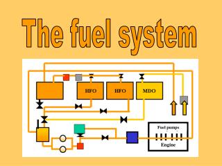
Oil Guns HOTV CV HORV
Ef oil Gun Cd oil gun Ab oil gun From pressurising pump house To storage tank Short recircultation line Long recirculation line
Oil gun Ignitor
Normal check up: 1.Fuel oil tank level is adequate. 2.6 m 2.suction tank temp adequate. (50-80 deg c.) 3.Heating steam is available. 4.Pump & heater is properly line up. 5.Re circulation line is line up. Routine check up: 1.Tank level (between 2.6 m to 85.m) 2.Tank temp(50-80 deg c) 3.Pump suction strainer DP(less than 1 ksc) 4.pump discharge pr(18-20 ksc) 5.Pump current (30-35 amps) 6.Heater outlet temp(120-130 deg c)