Download
1 / 27
300 likes | 548 Views
FUEL SYSTEM. Along the discussion please make a list of requirements to fuel system. Pureness of the fuel. High pressure pump and injectors Unit injectors Electronic unit injectors Contaminated fuel ruins the fine components. Sulphur. Converted to sulphur trioxide during combustion

E N D
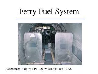
FUEL SYSTEM Along the discussion please make a list of requirements to fuel system
Pureness of the fuel • High pressure pump and injectors • Unit injectors • Electronic unit injectors Contaminated fuel ruins the fine components
Sulphur • Converted to sulphur trioxide during combustion • But react with liquid water. The result is H2SO4 – highly corrosive agent • React with Zn – White cloud of Zink sulphate
Water • Wears fuel system • Filter media go to swell cutting off the engine fuel supply • React with sulphur – H2SO4
Steps to overcome effects of water • Drain water from fuel tanks • Obtain fuel from reliable sources • Use water separators
Water separators • Sediment type
Water separators • Coalescing type
Catalytic Fines • Small , hard particles which originate at the refinery. • Cause very rapid abrasive wear on injection pumps, Piston rings and cylinder liners • Centrifuging and filtration
Micro organisms in Fuel • Cause corrosion and filter plugging • Bioside added to the fuel will kill them but not remove the remained of their bodies • Clean tanks and filter the fuel
Steps to minimize problem • Avoid long fuel storage periods • Drain water from fuel tanks regularly • Purchase fuel from reliable sources • Dose all fuel inventory with biocide at the first sign of micro organism contamination
Filters • Primary Fuel Strainer – 0.1x 0.2 mm • Secondary Fuel Filter – 10 microns Advised by engine manufacturer
Air in the fuel line Interruption of the flow
Heat in the fuel Power loss 1% of each 6 o C (10 o F) above 29o C (85 o F)
Fuel Coolers Factors affect the need for fuel cooling equipment: • Length of periods of continuous operation • Length of time between periods of operation • Volume of the fuel tank (larger than 11000L) • Ability of the fuel tanks to dissipate the heat of stored fuel
REQUIREMENTS • Pureness of the fuel • No air in the fuel line • No excessive heat in the fuel • As less restriction in the line as possible • Storage • If more then one tank – transfer • Stop flow when engine stop • How much fuel available • Isolating branch in case of contaminating
Fuel tanks • Size • How many tanks • Location • Materials • Requirements to the tank arrangement
Size • Fuel consumption f x hp (of kW) F = ------------------- S x 1000 S – Specific gravity of diesel fuel – 0.83 f – Specific fuel consumption: g/hp-hr or g/kW-hr F – Fuel consumption: l/hr • Proposed hours work without refill
How many tanks? • One – small boats • Two – Starboard and Port – stability maintenance • More than two • Day tank
Day tanks Factors affect the need for fuel cooling equipment: • Length of periods of continuous operation • Length of time between periods of operation • Volume of the fuel tank ( larger than 11000L) • Ability of the fuel tanks to dissipate the heat of stored fuel
Location of the day tank • The level of the fuel is to be no higher than the fuel injection valves on the engine • Close enough to the engine so the total suction lift is less than the suction head of the fuel pump.
Location • On the bottom or close to the hull side provides good cooling but could create too great stability • Close to the engine provide small resistance of the lines but weight distribution could suffer • Level – 1.Lower than engine injectors or shut off valve to be provided - solenoid or manual; 2.No lower than suction head of the fuel pump or transfer to additional higher tank is to be provided
Materials • Sheet steel • Marine aluminium • Nickel-copper • Fibreglass • Polyethylene Galvanized material should never be used Cu react with the sulphur in diesel as well
Requirements to the tank • Fill • Ventilation • Gauge • Drain • Cleaning access • Discharge line • Return line • Baffles • Grounding/Bonding
Fuel return line • Pressure limit – acc. manufacturer • Size at least same size as a supply line • A shutoff valve is not recommended
Test • 3 psi or more depends of rules complied Clean and flush fuel system prior to start the engine