Download
1 / 338
3.38k likes | 3.47k Views
Learn the levels of memory hierarchy - Cache, Main Memory, Secondary, and Tertiary Storage, virtual memory, disk mechanics, access characteristics, and accelerating secondary storage access.

E N D
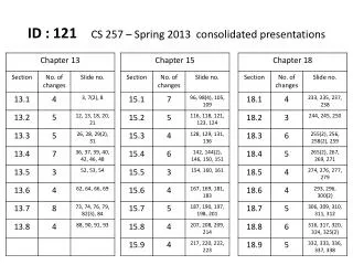
ID : 121 CS 257 – Spring 2013 consolidated presentations
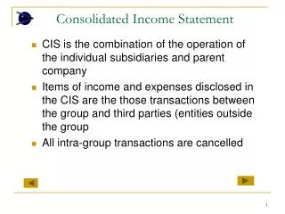
Secondary Storage Management The Memory Hierarchy
The Memory Hierarchy • Computer systems have several different components in which data may be stored. • Data capacities & access speeds range over at least seven orders of magnitude • Devices with smallest capacity also offer the fastest access speed & highest cost per byte
Description of Levels • Cache • Megabyte or more of Cache storage. • On-board cache : On same chip. • Level-2 cache : On another chip. • Cache data accessed in few nanoseconds. • Data moved from main memory to cache when needed by processor • Volatile
Description of Levels 2. Main Memory • 1 GB or more of main memory. • Instruction execution & Data Manipulation - involves information resident in main memory. • Time to move data from main memory to the processor or cache is in the 10-100 nanosecond range. • Volatile 3. Secondary Storage • Typically a magnetic disk. • Capacity upto 1 TB. • One machine can have several disk units. • Time to transfer a single byte between disk & main memory is around 10 milliseconds.
Description of Levels 4. Tertiary Storage • Holds data volumes measured in terabytes. • Significantly higher read/write times. • Smaller cost per bytes. • Retrieval takes seconds or minutes, but capacities in the petabyte range are possible.
Transfer of Data Between Levels • Data moves between adjacent levels of the hierarchy. • Each level is organized to transfer large amounts of data to or from the level below • Key technique for speeding up database operations is to arrange data so that when one piece of a disk block is needed, it is likely that other data on the same block will also be needed at about the same time. Summarize in single line (Add) Organization of disk
Volatile & Non Volatile Storage • A volatile device “forgets” what is stored in it when the power goes off. • Example: Main Memory • A nonvolatile device, on the other hand, is expected to keep its contents intact even for long periods when the device is turned off or there is a power failure. Convert to one liner • Example: Secondary & Tertiary Storage Note: No change to the database can be considered final until it has migrated to nonvolatile, secondary storage.
Virtual Memory • Managed by Operating System. • Some memory in main memory & rest on disk. • Transfer between the two is in units of disk blocks (pages). • Not a level of the memory hierarchy
Section 13.2 – Secondary storage management CS-257 Database System Principles Avinash Anantharamu 102
Index • 13.2 Disks • 13.2.1 Mechanics of Disks • 13.2.2 The Disk Controller • 13.2.3 Disk Access Characteristics
Disks: • The use of secondary storage is one of the important characteristics of a DBMS, and secondary storage is almost exclusively based on magnetic disks (Remove)
Structure of a Disk Reorder slides 15, 13, 14
Data in Disk • 0’s and 1’s are represented by different patterns in the magnetic material. • A common diameter for the disk platters is 3.5 inches.
Mechanics of Disks • Two principal moving pieces of hard drive 1- Head Assembly 2- Disk Assembly • Disk Assembly has 1 or more circular platters that rotate around a central spindle. • Platters are covered with thin magnetic material
Mechanics of Disks • Tracks are concentric circles on a platter. • Tracks are organized into sectors which are segments of circular platter. • Sectors are indivisible as far as errors are concerned. • Blocks are logical data transfer units.
Disk Controller • Control the actuator to move head assembly • Selecting the surface from which to read or write • Transfer bits from desired sector to main memory (Add) Buffering a track in local memory
Disk Access characteristics (Add) Accessing (reading or writing) a block requires three steps, and each step has an associated delay. • Seek time: The disk controller positions the head assembly at the cylinder containing the track on which the block is located. The time to do so is the seek time. • Rotational latency: The disk controller waits while the first sector of the block moves under the head. This time is called the rotational latency.
Disk Access characteristics • Transfer time: All the sectors and the gaps between them pass under the head, while the disk controller reads or writes data in these sectors. (Remove)This delay is called the transfer time. • Latency of the disk: The sum of the seek time, rotational latency, transfer time is the latency of the time.
13.3 Accelerating Access to Secondary Storage San Jose State University Spring 2012
13.3 Accelerating Access to Secondary StorageSection Overview • 13.3.1: The I/O Model of Computation • 13.3.2: Organizing Data by Cylinders • 13.3.3: Using Multiple Disks • 13.3.4: Mirroring Disks • 13.3.5: Disk Scheduling and the Elevator Algorithm • 13.3.6: Prefetching and Large-Scale Buffering
13.3 Introduction • Average block access is ~10ms. • Disks may be busy. • Requests may outpace access delays, leading to infinite scheduling latency. • There are various strategies to increase disk throughput. • The “I/O Model” is the correct model to determine speed of database operations
13.3 Introduction (Contd.) • Actions that improve database access speed: • Place blocks closer, within the same cylinder • Increase the number of disks • Mirror disks • Use an improved disk-scheduling algorithm • Use prefetching
13.3.1 The I/O Model of Computation • If we have a computer running a DBMS that: • Is trying to serve a number of users • Has 1 processor, 1 disk controller, and 1 disk • Each user is accessing different parts of the DB • It can be assumed that: Dominance of I/O cost • Time required for disk access is much larger than access to main memory; and as a result: • The number of block accesses is a good approximation of time required by a DB algorithm
13.3.2 Organizing Data by Cylinders • It is more efficient to store data that might be accessed together in the same or adjacent cylinder(s). • In a relational database, related data should be stored in the same cylinder.
13.3.3 Using Multiple Disks • If the disk controller supports the addition of multiple disks and has efficient scheduling, using multiple disks can improve performance significantly • By striping a relation across multiple disks, each chunk of data can be retrieved in a parallel fashion, improving performance by up to a factor of n, where n is the total number of disks the data is striped over • Summarize. Too long.
13.3.4 Mirroring Disks • A drawback of striping data across multiple disks is that you increase your chances of disk failure. Rewrite - striping data across multiple disks, increase chances of disk failure • To mitigate this risk, some DBMS use a disk mirroring configuration • Disk mirroring makes each disk a copy of the other disks, so that if any disk fails, the data is not lost • Since all the data is in multiple places, access speedup can be increased by more than n since the disk with the head closest to the requested block can be chosenunclear - rewrite
13.3.5 Disk Scheduling • One way to improve disk throughput is to improve disk scheduling, prioritizing requests (remove)such that they are more efficient • The elevator algorithm is a simple yet effective disk scheduling algorithm • The algorithm makes the heads of a disk oscillate back and forth similar to how an elevator goes up and down • The access requests closest to the heads current position are processed first
13.3.5 Disk Scheduling • When sweeping outward, the direction of head movement changes only after the largest cylinder request has been processed • When sweeping inward, the direction of head movement changes only after the smallest cylinder request has been processed • Example:
13.3.6 Prefetching and Large-Scale Buffering • In some cases we can anticipate what data will be needed • We can take advantage of this by prefetching data from the disk before the DBMS requests it • Since the data is already in memory, the DBMS receives it instantly
Disk Failures Presented by Timothy Chen Spring 2013
Index • 13.4 Disk Failures 13.4.1 Intermittent Failures 13.4.2 Organizing Data by Cylinders 13.4.3 Stable Storage 13.4.4 Error- Handling Capabilities of Stable Storage 13.4.5 Recovery from Disk Crashes 13.4.6 Mirroring as a Redundancy Technique 13.4.7 Parity Blocks 13.4.8 An Improving: RAID 5 13.4.9 Coping With Multiple Disk Crashers
Intermittent Failures • If we try to read the sector but the correct content of that sector is not delivered to the disk controller • Controller will check good and bad sector • If the write is correct: Read is performed • Good sector and bad sector is known by the read operation (Add) slide – define intermittent failure, media decay, write failure and disk crash (page 575)
CheckSum • Read operation that determine the good or bad status Combine with next slide
How CheckSum perform • Each sector has some additional bits • Set depending on the values of the data bits stored in each sector • If the data bit in the not proper we know there is an error reading • Odd number of 1: bits have odd parity(01101000) • Even number of 1: bit have even parity (111011100) • Find Error is the it is one bit parity
Stable Storage • Deal with disk error • Sectors are paired and each pair X showing left and right copies as Xl and Xr • It check the parity bit of left and right by subsituting spare sector of Xl and Xr until the good value is returned Too vague: make two sections to define problem and solution
Error-Handling Capabilities of Stable Storage • Since it has XL and XR, one of them fail we can still read other one • Chance both of them fail are pretty small • The write Fail, it happened during power outage Too vague: write in two sections media failure and write failure
Recover Disk Crash • The most serious mode of failure for disks is “head crash” where data permanently destroyed. • The way to recover from crash , we use RAID method
Mirroring as a Redundancy Technique • it is call Raid 1 • Just mirror each disk Unclear – too vague
Parity Block • It often call Raid 4 technical • read block from each of the other disks and modulo-2 sum of each column and get redundant disk disk 1: 11110000 disk 2: 10101010 disk 3: 00111000 get redundant disk 4(even 1= 0, odd 1 =1) disk 4: 01100010
Parity Block- Fail Recovery • It can only recover one disk fail • If it has more than one like two disk • Then it can’t be recover us modulo-2 sum Rephrase – not understandable
Coping with multiple Disk Crash • For more one disk fail • Either raid 4 and raid 5 can’t be work • So we need raid 6 • It is need at least 2 redundant disk Rephrase - Not understandable
Secondary Storage Management 13.5 Arranging data on disk Mangesh Dahale ID-105 CS 257