Download
1 / 9
90 likes | 124 Views
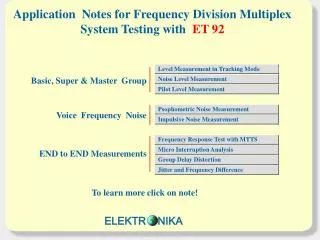
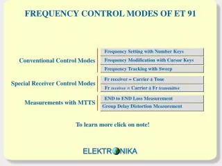
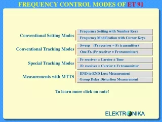
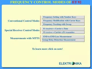
FREQUENCY CONTROL MODES OF ET 9 2. Frequency Setting with Number Keys. Frequency Modification with Cursor Keys. Frequency Tracking with Sweep. Fr receiver = Carrier ± Tone. Fr receiver = Carrier ± Fr transmitter. END to END Loss Measurement. Group Delay Distortion Measurement.

E N D
FREQUENCY CONTROL MODES OFET 92 Frequency Setting with Number Keys Frequency Modificationwith Cursor Keys Frequency Tracking with Sweep Fr receiver = Carrier ± Tone Fr receiver = Carrier ± Fr transmitter END to END Loss Measurement Group Delay Distortion Measurement To learn more click on note! ELEKTR NIKA
Frequency Setting with Number Keys Option Option Option To set a new frequency use the NUMBER keys as usual. E.g. 3825 Hz Notice: don’t touch the cursor keys ELEKTR NIKA
Frequency Modification with Cursor Keys Option Option Option FREQU: 100.000 kHz FREQU: 100.000 kHz FREQU: 100.000 kHz FREQU: 100.000 kHz FREQU: 100.100 kHz FREQU: 100.200 kHz The frequency STEP can be modified with the HORIZONTAL cursor keys The FREQUENCY can be modified with the VERTICAL cursor keys Notice: don’t touch the number keys ELEKTR NIKA
Frequency Tracking with Sweep Option Option Option For Options For Next/Loss Selectable ranges ELEKTR NIKA
Receiver Frequency Setting in Carrier ± Tone Format Test instructions of FDM systems often specify the test frequency in format: Carrier ± Channel ( Tone) Frequency. ET 92 provides the separate setting of carrier and tone frequencies and so: No frequency calculation is required! Select mode Final display format Set carrier Set tone ELEKTR NIKA
Special Transmitter Tracking Mode Often used test procedure of FDM equipment is: ■ feeding audio frequency test signal to the input of the tested channel ■ measuring the level of modulation product at a high frequency test point In that case: Receiver Frequency (Rx)= Carrier ± Transmitter Frequency (Tx) ET 92 provides a special transmitter tracking mode. In that special mode: ■ The frequency range of transmitter: 200Hz to 4 kHz ■The level meter is controlled by the generator according to the above mentioned rule. ADVANTAGES:No frequency calculation is required ! Only one frequency setting is required ! ELEKTR NIKA
END to END Loss Measurements with MTTS MTTS METHOD: ■The transmitter generates 35 test tones ■The receiver measures the 35 test tones simultaneously ADVANTAGES: ■No synchronisation is necessary between the two instruments ■The measuring time is shorter than that of other methods ELEKTR NIKA
Group Delay Distortion Measurement with MTTS ET 92 applies the multi tone test method described in Recommendation ITU-T O.81 Appendix I MTTS METHOD: The transmitter generates 36 test tones ■ Frequency range: 100 to 3600 Hz ■Frequency step: 100 Hz ■Level: -20 dBm / frequency The receiver measures the 36 test tones simultaneously ADVANTAGES: ■No synchronisation is necessary between the two instruments ■Group delay and signal level measurement at the same time ■The measuring time is shorter than that of other methods ELEKTR NIKA