Download
1 / 43
440 likes | 610 Views
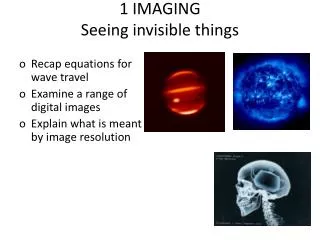
Imaging Procedure 1. Final Revision. Main Factors Affecting Recorded Image Detail. kVp & mAs Motion Object Unsharpness Focal Spot Size SID (Source to Image Distance) OID (Object to Image Distance) Material Unsharpness. Size Distortion & OID.

E N D
Imaging Procedure 1 Final Revision
Main Factors Affecting Recorded Image Detail • kVp & mAs • Motion • Object Unsharpness • Focal Spot Size • SID (Source to Image Distance) • OID (Object to Image Distance) • Material Unsharpness
Size Distortion & OID • If source is kept constant, OID will affect magnification • As OID , magnification • The farther the object is from the film, the more magnification
Image Distortion • When the part to be imaged – does not lay parallel with the IR (cassette) • If the Central Ray is not perpendicular to the part
FOCAL SPOT ANGLE SMALLER ANGLE – SMALLER BEAM AT PATIENT
Film Speed / Crystal size • Larger crystals or Thicker crystal layer Faster response= less detail, and less exposure (chest x-ray) • Finer crystals / thinner crystal layer =Slower response, greater detail, more exposure (extremity)
Axial Skelton- 80 bones • Cranium-8 • Facial-14 • Hyoid-1 • Auditory ossicles-6 • Cervical vert.-7 • Thoracic vert.-12 • Lumbar vert.-5 • Sacrum-1 • Coccyx-1 • Sternum-1 • Ribs-24 Total-80
Anatomic Position • Upright, arms adducted, palms forward, head and feet directed straight ahead • Viewing Radiographs: Display x-rays so that the patient is facing the viewer in anatomic position R
Body Surfaces and Parts • Posterior or dorsal • Anterior or ventral • Plantar- sole of foot • Dorsal- top of anterior surface of foot, back or posterior aspect of hand • Palmar- palm of hand or the anterior/ventral surface
Image Markers and Patient ID • All films should have two markers: • Patient ID and date • Anatomic side markers R or L
Most Useful Applications for Plain X-Rays • Chest • Musculoskeletal • Abdomen: limited usefulness
Main Uses of Fluoroscopy • Gastrointestinal Imaging • Genitourinary Imaging • Angiography • Other • Intraoperative • Foreign body removal • Musculoskeletal
Upper GI Exam • Evaluates esophagus, stomach and duodenum • Double or Single Contrast • Can be combined with small bowel series • Largely replaced by endoscopy and cross-sectional imaging • Fairly insensitive
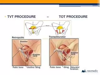
Cystogram • Usually in adult patients • Looking for tear or intraluminal mass • Catheter placed and bladder filled with contrast to capacity: usually 300-500 ml. • Spot films obtained when full • Post void film: usually overhead
Cystogram Cystogram with Intraperitoneal Rupture
Techniques - Projection P-A (relation of x-ray beam to patient)
Techniques - Projection (continued) Decubitus
Heart Right border: Edge of (r) Atrium 3. Left border: (l) Ventricle + Atrium 4. Posterior border: Reft Ventricle 5. Anterior border: Right Ventricle
Heart Size:
Heart Size of heart Size of individual chambers of heart Size of pulmonary vessels Evidence of stents, clips, wires and valves Outline of aorta and IVC and SVC
Procedure • Apply proper compression to produce uniform breast thickness • Essential to high-quality mammograms • Place ID markers
Routine mammography projections Craniocaudal (CC) Mediolateral oblique (MLO)
CT Protocolling • Variables • Plain or contrast enhanced • Slice positioning • Slice thickness • Slice orientation • Slice spacing and overlap • Timing of imaging and contrast administration • Reconstruction algorhithm • Radiation dosimetry
CT Terminology • Window Width • Number of Hounsfield units from black to white • Level or Center • Hounsfield unit approximating mid-gray
Clinical Applications • Multisection CT aquires changes in the planning and staging of patient examinations. The scanning time is reduced for most examinations, requiring adjustments in the administration of intravenous contrast material. The amount of contrast material can be reduced, and different vascular phases can be better visualized. Thin-section scanning allows production of high-quality MPR images
Couinaud’s hepatic segments divide the liver into eight segments . The hepatic veins are the longitudinal boundaries . The transverse plane is defined by the right and left portal pedicles .
Sonographic Evaluation of the Liver • Evaluation of the hepatic structure is one of the most important procedures in sonography for many reasons. The normal , basiclly homogenerous parenchyma of the liver allows imaging of the neighboring anatomic structures in the upper abdomen.
The appropriate transducer depends on the patient’s body habitus and size • The average adult abdomen usually requires a 3.5MHz
f f0 (RBC) • Doppler ultrasound is used primarily to identify and evaluate blood flow in vessels • velocity and waveform information can be used to evaluate stenoses, resistance • and vessel patency Doppler Frequency Shift (fD) doppler frequency shift (fD) =change in frequency = (f0 - f) where f0 is the original frequency and f is the frequency of the returning echo (from RBC) • maximum shift is obtained when = 0° • minimum shift is obtained when = 90° (recall, imaging of strongest echoes) • the shift is comparatively small and typically is between 0 - 15 kHz (audible sound) • the shift is positive when the RBC is moving towards the transducer and is negative • when the RBC is moving away from the transducer
Color Flow Doppler • Color Doppler is a hybrid that combines anatomicnobtained using • B-mode system with flow information obtained using pulsed Doppler analysis • colors (blue and red) are assigned dependent on motion (toward or away) from the • transducer • turbulence (i.e.: variations in flow direction) can vary between green and yellow • the depth of each color varies with the velocity of flow, stationary tissues appear gray • information is provided over a large area and superimposed on a gray scale image • color Doppler can detect flow in vessels too small to see by imaging alone • spectral analysis may also be obtained using commercial color Doppler systems • modern instruments incorporate both color Doppler and spectral Doppler
Oxygen, hydrogen, carbon, nitrogen elements constitute 96 % of human body mass. Oxygen is 65 % of body mass; carbon is 18.5 %, hydrogen 9.5 %, nitrogen 3.2 %. Let us ignore all elements but Hydrogen.