Active Filters
Active Filters. Conventional passive filters consist of LCR networks. Inductors are undesirable components: They are particularly non-ideal (lossy) They are bulky and expensive Active filters replace inductors using op-amp based equivalent circuits. Active Filter Designs.

Active Filters
E N D
Presentation Transcript
Active Filters • Conventional passive filters consist of LCR networks. • Inductors are undesirable components: • They are particularly non-ideal (lossy) • They are bulky and expensive • Active filters replace inductors using op-amp based equivalent circuits.
Active Filter Designs Three active filter design techniques will be covered: • Synthesis by Sections • Cascade of second order sections. • Component Simulation • Replace inductors with op-amp inductor simulations. • Operational Simulation • Simulate all currents and voltages in the LCR ladder using an analogue computer.
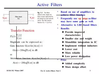
Analogue Filter Responses H(f) H(f) 0 0 f f fc fc Ideal “brick wall” filter Practical filter
Standard Transfer Functions • Butterworth • Flat Pass-band. • 20n dB per decade roll-off. • Chebyshev • Pass-band ripple. • Sharper cut-off than Butterworth. • Elliptic • Pass-band and stop-band ripple. • Even sharper cut-off. • Bessel • Linear phase response – i.e. no signal distortion in pass-band.
Special case when M=0, all-pole response : Analogue Transfer Functions The transfer function of any analogue filter (active or passive) can be expressed as the ratio of two polynomials :
Poles and Zeros • Poles • Complex values of s where the transfer function is infinite. • i.e. the denominator of the transfer function is zero. • Zeros • Complex values of s where the transfer function is zero. • An N-th order filter will have N poles and up to N zeros. • Some poles may be in the same place (as may some zeros).
Example – Two Pole Bessel Filter Low pass, cut-off frequency = 1 rad/s, from tables :
Operational Amplifiers • All the active filters we shall study are based on operational amplifiers (op-amps). • Analysis of linear op-amp circuits is usually based on simplifying assumptions : • The difference between the non-inverting and inverting inputs is zero. • The input current is zero. • The output voltage and current is arbitrary.
Op-Amp Assumptions I+ V+ + Iout Vout I- V- -
Inverting Amplifier Z2 Z1 VIN - VOUT + 0 V
Non-Inverting Amplifier VIN + VOUT - Z1 Z2 0 V
Buffer Amplifier • Output voltage = Input voltage • Input impedance is infinite • Output impedance is zero VIN + VOUT -
Single-Pole Passive Filter • First order low pass filter • Cut-off frequency = 1/CR rad/s • Problem : Any load (or source) impedance will change frequency response. R C vin vout
Single-Pole Active Filter • Same frequency response as passive filter. • Buffer amplifier does not load RC network. • Output impedance is now zero. R C vin vout
Low-Pass and High-Pass Designs High Pass Low Pass
Higher Order Filters • You might think we could make higher order filters by simply cascading N first order filters • This doesn’t work • The single pole of a first order filter must be purely real (no imaginary part) • The poles of a higher order filter usually need to be complex • Solution: Use second order sections, each one synthesising a conjugate pair of complex poles
Summary • Active filter designs aim to replace the inductors in passive filters. • Design techniques : • Synthesis by sections • Component simulation • Operational simulation • All based on op-amps – understanding of basic op-amp circuits is essential.