Active Filters
590 likes | 1.71k Views
Active Filters. Based on use of amplifiers to achieve filter function Frequently use op amps so filter may have some gain as well. Alternative to LRC-based filters Benefits Provide improved characteristics Smaller size and weight Monolithic integration in IC

Active Filters
E N D
Presentation Transcript
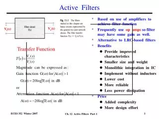
Active Filters • Based on use of amplifiers to achieve filter function • Frequently use op amps so filter may have some gain as well. • Alternative to LRC-based filters • Benefits • Provide improved characteristics • Smaller size and weight • Monolithic integration in IC • Implement without inductors • Lower cost • More reliable • Less power dissipation • Price • Added complexity • More design effort Vo(s) Vi(s) Transfer Function Ch. 12 Active Filters Part 1
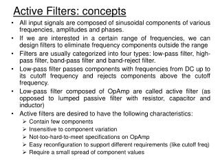
Filter Types • Four major filter types: • Low pass(blocks high frequencies) • High pass(blocks low frequencies) • Bandpass (blocks high and low frequencies except in narrow band) • Bandstop(blocks frequencies in a narrow band) Low Pass High Pass Bandpass Bandstop Ch. 12 Active Filters Part 1
Filter Specifications • Specifications - four parameters needed • Example – low pass filter: Amin, Amax, Passband, Stopband • Parameters specify the basic characteristics of filter, e.g. low pass filtering • Specify limitations to its ability to filter, e.g. nonuniform transmission in passband, incomplete blocking of frequencies in stopband Ch. 12 Active Filters Part 1
Filter Transfer Function • Any filtertransfer function T(s) can be written as a ratio of two polynomials in “s” • Where M < N and N is called the “order” of the filter function • Higher N means better filter performance • Higher N also means more complex circuit implementation • Filter transfer function T(s) can be rewritten as • where z’s are “zeros” and p’s are “poles” of T(s) • where poles and zeroes can be real or complex • Form of transfer function is similar to low frequency function FL(s)seen previously for amplifiers where A(s) = AMFL(s)FH(s) Ch. 12 Active Filters Part 1
First Order Filter Functions * First order filter functions are of the general form Low Pass a1 = 0 High Pass a0 = 0 Ch. 12 Active Filters Part 1
First Order Filter Functions * First order filter functions are of the form General a1 0, a2 0 All Pass Ch. 12 Active Filters Part 1
Example of First Order Filter - Passive • Low Pass Filter 0 dB Ch. 12 Active Filters Part 1
Example of First Order Filter - Active • Low Pass Filter I1 = Io Io V_= 0 Gain Filter function 20 log (R2/R1) Ch. 12 Active Filters Part 1
Second-Order Filter Functions j * Second order filter functions are of the form which we can rewrite as where o and Q determine the poles * There are seven second order filter types: Low pass, high pass, bandpass, notch, Low-pass notch, High-pass notch and All-pass s-plane x o x This looks like the expression for the new poles that we had for a feedback amplifier with two poles. Ch. 12 Active Filters Part 1
Second-Order Filter Functions Low Pass a1= 0, a2= 0 High Pass a0= 0, a1= 0 Bandpass a0= 0, a2= 0 Ch. 12 Active Filters Part 1
Second-Order Filter Functions Notch a1= 0, ao = ωo2 Low Pass Notch a1= 0, ao > ωo2 High Pass Notch a1= 0, ao < ωo2 All-Pass Ch. 12 Active Filters Part 1
Passive Second Order Filter Functions • Second order filter functions can be implemented with simple RLC circuits • General form is that of a voltage divider with a transfer function given by • Seven types of second order filters • High pass • Low pass • Bandpass • Notch at ωo • General notch • Low pass notch • High pass notch Ch. 12 Active Filters Part 1
Example - Passive Second Order Filter Function • Low pass filter T(dB) Q 0 dB General form of transfer function 0 Ch. 12 Active Filters Part 1
Example - Passive Second Order Filter Function • Bandpass filter T(dB) 0 dB -3 dB General form of transfer function 0 Ch. 12 Active Filters Part 1
Single-Amplifier Biquadratic Active Filters • Generate a filter with second order characteristics using amplifiers, R’s and C’s, but no inductors. • Use op amps since readily available and inexpensive • Use feedback amplifier configuration • Will allow us to achieve filter-like characteristics • Design feedback network of resistors and capacitors to get the desired frequency form for the filter, i.e. type of filter, e.g bandpass. • Determine sizes of R’s and C’s to get desired frequency characteristics (0 and Q), e.g. center frequency and bandwidth. • Note: The frequency characteristics for the active filter will be independent of the op amp’s frequency characteristics. Example - Bandpass Filter General form of transfer function Ch. 12 Active Filters Part 1
Design of the Feedback Network • General form of the transfer function for feedback network is • Loop gain for feedback amplifier is • Gain with feedback for feedback amplifier is • Poles of feedback amplifier (filter) are found from setting Conclusion: Poles of the filter are the same as the zeros of the RC feedback network ! Design Approach: 1. Analyze RC feedback network to find expressions for zeros in terms R’s and C’s. 2. From desired 0and Q for the filter, calculate R’s and C’s. 3. Determine where to inject input signal to get desired form of filter, e.g. bandpass. Ch. 12 Active Filters Part 1
Design of the Feedback Network • Bridged-T networks (2 R’s and 2C’s) can be used as feedback networks to implement several of the second order filter functions. • Need to analyze bridged-T network to get transfer function t(s) of the feedback network. We will show that • Zeros of this t(s) will give the pole frequencies for the active filter.. Bridged – T network General form of filter’s transfer function Ch. 12 Active Filters Part 1
Analysis of t(s) for Bridged-T Network Analysis for t(s) = Va / Vb I3 = (Vb-Va)/R3 I2 = I3 I1 Ia = 0 V12 Va Vb I4 Ch. 12 Active Filters Part 1
Analysis of Bridged-T Network • Setting numerator of t(s) = 0 gives zeroes of t(s), which are also the poles of filter’s transfer function T(s) since • Where the general form of filter’s T(s) is • Then comparing the numerator of t(s) and the denominator of T(s), o and Q are related to the R’s and C’s by • so • Given the desired filter characteristics specified by o and Q, the R’s and C’s can now be calculated to build the filter. These have the same form – a quadratic ! Ch. 12 Active Filters Part 1