Download
1 / 60
600 likes | 604 Views
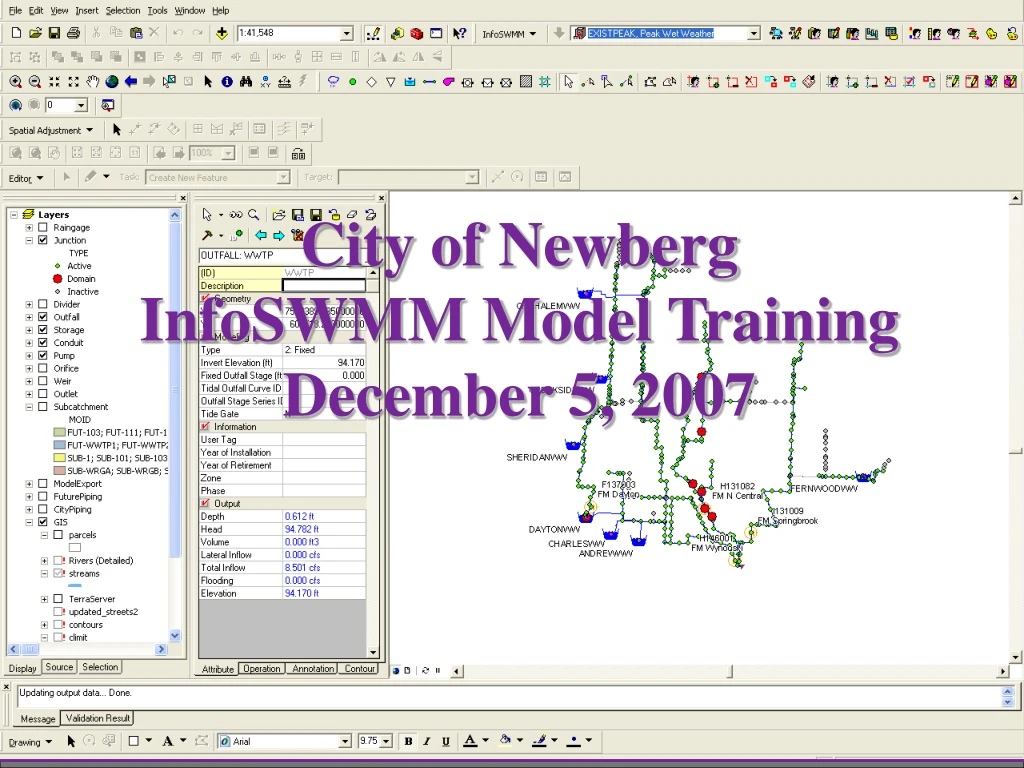
City of Newberg InfoSWMM Model Training December 5, 2007. Model Training InfoSWMM Product Overview InfoSWMM Project (Data Model) Creating/Modifying an InfoSWMM Model Hydraulic Model Parameters Domain and Facility Management Running Simulations/Viewing Results Scenario Management

E N D
City of Newberg InfoSWMM Model Training December 5, 2007
Model Training InfoSWMM Product Overview InfoSWMM Project (Data Model) Creating/Modifying an InfoSWMM Model Hydraulic Model Parameters Domain and Facility Management Running Simulations/Viewing Results Scenario Management Importing & Exporting Data Additional InfoSWMM Features Examples Discussion/Questions Agenda
InfoSWMM Features Graphical Model Creation Scenario Management Appurtenance Controls Pumps / Real Time Control Model Result Analysis Integration with other Information Systems 1. InfoSWMM Overview Features
InfoSWMM Features Importing Data Import Manager Network Review Trace Network Locate Disconnected Links/Nodes Fix Connectivity Data Entry/Editing Attribute Browser DB Editor 1. InfoSWMM Overview Features
InfoSWMM Features Model Review Graphs Reports Thematic Mapping Animation 1. InfoSWMM Overview Features
Extension for ArcView 8.2 or above Share data with other utility information systems Share graphs, reports, and model results with other Windows-based products 1. InfoSWMM Overview Interaction with Other Software
Each project contains: Network scenarios Network map Network component attributes Modeling parameters Model solution and results Additional elements: Graphs Contours Reports Files for data exchange 2. InfoSWMM ProjectOverview
Network schematic: Stored as .MXD file Newberg_HydraulicModel_Dec07.mxd Database tables and modeling files Model Training\Newberg_HydraulicModel_Dec07.ISDB One directory containing model results *.OUT folder created after a successful simulation run 2. InfoSWMM ProjectProject Storage Structure
Newberg Model Junctions Storage Conduits Pumps Outfall Other Components Weirs, Orifices, Dividers, Subcatchments, Raingages 2. InfoSWMM ProjectProject Components
Junctions 353 Junctions in Newberg Model Represent flow into the system from Subcatchments External or DWF RDII Can serve as storages during surcharge conditions 2. InfoSWMM Project Components - Junctions
Storages 7 Storages in Newberg Model Represent wet wells in Newberg Model Outflow controlled by: Real Time Controls on Pumps Can receive inflows 2. InfoSWMM Project Components - Storages
Conduits 354 Conduits in Newberg Model Convey water between nodes May be drawn in parallel Direction is critical Must have a junction, storage, divider, or outfall at endpoints Over 20 shapes available Only Circular used in Newberg 2. InfoSWMM ProjectComponents - Conduits
Pumps 19 Pumps in Newberg Model (including lag pumps) Flow from wet well node to downstream node Can control pump status with operational controls Used wet well levels to control pump on/off levels 4 pump curve types available for defining performance Type 3 used for all Newberg Pumps Type 3: Flow varies continuously with head difference between the inlet and outlet nodes 2. InfoSWMM ProjectComponents - Pumps
Outfall 1 Outfall in Newberg Model (WWTP) Point where flow leaves the system Boundary conditions during dynamic wave simulations: Free, Normal, Fixed, Tidal, Time Series Newberg model used Fixed: Outfall stage is set to a fixed value Invert: 94.17 ft Stage: 0 Draining into a wet well at a lift station at the plant The 0 means that the depth is 0 feet above the invert The 94.17 is the high water level at the pump station 2. InfoSWMM ProjectComponents - Outfall
Model results for nodes Hydraulic Grade Inflow Rates Flooding Rate Storage Volume Model results for links Flow rate Velocity Water depth Q/Qmax ratio 2. InfoSWMM ProjectModel Results
2. InfoSWMM ProjectModeling Environment Build/Modify Network InfoSWMM Drop Down Menu Simulation Buttons Attribute Browser
2. InfoSWMM ProjectToolbars/Menu Organization ArcMAP Toolbar Results Map Display InfoSWMM Toolbar Domain Build/Modify Network See Also Page 2-34 of Training Manual
2. InfoSWMM ProjectModeling Environment/Browser Attribute Data Operation Data Attribute Data Operation Data Annotation Center Contour
2. InfoSWMM ProjectBrowser/Operation Data Simulation Options Pump Curves Time Patterns Time Series
Initialize Project Initialize InfoSWMM 3. Modifying InfoSWMM ModelOpening Model File InfoSWMM Drop Down Menu
Basic Model Options for Newberg Flow Units:cfs Routing Method: Dynamic Other Options (not used for Newberg) Infiltration Model: Green Ampt (Default) Runoff Model: EPA SWMM (Default) 3. Modifying InfoSWMM ModelBasic Model Options
Preference Dialog Operation Settings Display Settings Application Settings Labeling ID and Description Default Symbol Size 3. Modifying InfoSWMM ModelPreferences and Default Values
3. Modifying InfoSWMM ModelAdding Nodes – Attribute Browser • Attribute Browser - Nodes • ID • Unique value identifying node from Newberg GIS • Geometry • X and Y coordinates from Newberg GIS • Modeling Data • Hydraulic Parameters • From Newberg GIS • Information • General Information • Not used when running the model • Output • Only available after running simulation
3. Modifying InfoSWMM ModelAdding Conduits – Attribute Browser • Attribute Browser - Conduits • ID • Unique value identifying node from Newberg GIS • Geometry • Start and end nodes • Modeling Data • Hydraulic Parameters • Max Depth = Diameter (ft) • Information • General Information • Not used when running the model • Output • Only available after running simulation • Need to create Nodes before Conduits • Draw conduit between Nodes and start and end automatically updated
3. Modifying InfoSWMM ModelModifying Network Components • Used for Newberg • Move Nodes • Redraw Links • Edit Link Vertex • Not used in Newberg • Edit Subcatchment Vertex • Move Subcatchment
3. Modifying InfoSWMMDatabase Editor • Element Hydraulic/Hydrologic Data • Element Information Data • Element Geometry and Connectivity Data • Hydrologic Data • Quality Data • Real Time Control Data • Curve, Pattern, and Time Series Data • Simulation Settings • Advanced Application Data
3. Modifying InfoSWMMDatabase Editor • DB Editor Uses: • Editing a selected set of features • Copy and Paste into/from Excel • Statistical Analysis of Input Data
3. Modifying InfoSWMMDatabase Editor/Functions • Database Functions • Block Edit • Field Calculator • Field Statistics
3. Modifying InfoSWMMDatabases Element Hydraulic/Hydrologic Data • Junction Hydraulic (Modeling) Data • Outfall Hydraulic (Modeling) Data • Storage Hydraulic (Modeling) Data • Conduit Hydraulic (Modeling) Data • Pump Hydraulic (Modeling) Data
3. Modifying InfoSWMMJunction Hydraulic Data Junction Hydraulic (Modeling) Data • Invert Elev. (ft), Max. Depth (ft), Surcharge Depth (ft), Ponding Area (ft2) • Surcharge Depth – set to 1,000 at pump station wet wells • Ponding Area – default to 1,000 ft2 to allow enough area for ponding
3. Modifying InfoSWMMOutfall Hydraulic Data Outfall Hydraulic Modeling Data • Type, Invert Elev. (ft)
3. Modifying InfoSWMMStorage Hydraulic Data Storage Hydraulic (Modeling) Data • Invert Elev. • Max Depth = Height of Wet Well (ft) • Storage Shape Type = Functional • Exponent of Storage = Constant at 1 • Constant for Storage = Area of Wet Well (ft2)
3. Modifying InfoSWMMConduit Hydraulic Data Conduit Hydraulic Modeling Data • Length, Manning’s N, Downstream Offset (ft), Shape Type, Max Depth (ft) • Downstream Offset • Inverts are specified at MH’s • Inverts were set to “out” invert elev. • Adjust the downstream offset to reflect the “in” invert elev.
3. Modifying InfoSWMMPump Hydraulic Data Pump Hydraulic (Modeling) Data • Pump ID and Pump Curve ID • Pump ID Curves Generated in “Operation” Control Center
3. Modifying InfoSWMMElement Information Element Information Data • Descriptive information about each model element: • Description • Year of Installation • Year of Retirement • Zone • Phase • No information was entered • Not used in modeling
3. Modifying InfoSWMMGeometry and Connectivity Element Geometry & Connectivity Data • Node Geometry: • X,Y Coordinates • Link Connectivity • From NODE ID • To NODE ID • CAL_Length (model calculated length)
3. Modifying InfoSWMMExtended Element Hydraulic Data Extended Element Hydraulic Data • Junction Inflow: • Not Used • Junction DWF • Modeled Flow (Baseflow, GWI, & RDII) • Junction RDII • Not Used
3. Modifying InfoSWMMJunction DWF Junction Dry Weather Flow (DWF) • DWF Item: • FLOW • Average DWF Value: • flow rate (cfs) • Pattern: • Diurnal, GWI, or RDII • Alloc_Code: • Indicates what flow is represented
4. Hydraulic Model ParametersCurves • Curves: • One for each pump station
4. Hydraulic Model ParametersTime Series/Patterns • Time Series/Patterns: • Patterns for Basin Diurnal • GWI • RDII Time Patterns
4. Hydraulic Model ParametersCommon Buttons for Options, Curves, Time Series, Patterns & RTC See Model/Training Manual page 4-18
5. Domain & Facility ManagementDomain Management • Domain Management • Domain: A group of selected features for data editing or result display • Created with: • User Selection • Queries • Selection Sets
5. Domain & Facility ManagementDomain Management • Newberg Domains • Flow Meters • Profile sets
6. Running Simulations/Viewing ResultsRun Manager Run Manager • Run Simulations • Load and save output records
6. Running Simulations/Viewing ResultsOutput Unit Manager Output Unit Manager • Changes output units: • Reports • Graphs • Contours • Labels
6. Running Simulations/Viewing ResultsReport Manager Report Manager • Edit/Manage all output reports and graphs: • Changes styles of text & titles • Copy graphs to clipboard • Save graphs as images • Copy/Paste reports into Excel
6. Running Simulations/Viewing ResultsOutput Report & Graph Create output reports & graphs • Select graph or report type • Junction Summary • Max Depth & HGL • Conduit Summary • Max Flow, Max q/Q, Max d/D • Chose Elements • Selection sets helpful for looking at select areas • Specify a time frame