Download
1 / 9
90 likes | 220 Views
Enhancements to the Linac Coherent Light Source. LCLS Strategic Plan. Near term - 2 years “LCLS-I” Increase user capacity flexible beam delivery through optics, linac energy and pulse length changes fixed gap afterburner at second harmonic 16 keV. Intermediate term – 5 years “LCLS-II”

E N D
LCLS Strategic Plan • Near term - 2 years “LCLS-I” • Increase user capacity • flexible beam delivery through optics, linac energy and pulse length changes • fixed gap afterburner at second harmonic 16 keV Intermediate term – 5 years “LCLS-II” Same injector, last 1/3 of linac, same conventional facilities Implement full capacity:simultaneous use of 6 hutches Increase spectral capability:present 800eV - 8keV, future 500eV - 24keV Implement polarization control Implement seeding Long term – 10 years “LCLS-III” Expansion: additional injectors, linac sections, undulators, conventional facilities higher rep. rate, linac energy, pulse properties, number of stations
Increased energy range toward transform limited pulses LCLS upgrade – “LCLS-II”
LCLS-II: 3 Phases over 5 years 2-pulse 2-color 6-60 Å adjust. gap EEHG*? 6-60 Å adjust. gap full polarization control full polarization control 5 m 4-GeV bypass self-seeding option full polarization control self-seeding HXR option (2 bunches) 0.75 Å adjustable gap 0.5-15 Å 4-GeV SXR and 14-GeV HXR simultaneous op’s with bypass line SXR1 (40 m) SXR2 (40 m) 5 m FEE-2 240 nm 6 nm 4-14 GeV new adj. gap und. (0.5-15 Å) Shortened 74-m Undulator SHAB 30 m 5 m Existing 112-m Undulator (1.5-15 Å) FEE-1 Phase-2 Phase-3 Existing Phase-1 No civil construction. Uses existing beam energy and quality. * Phys. Rev. Lett. 102, 074801 (2009)
Summary of three Phases • Phase-1 (2nd Harmonic Afterburner) • Existing 1.5-15 Å capabilities fully preserved • Quick path to 2nd harmonic (0.75 Å) with afterburner (1-2 GW) • Full polarization control of 1st or 2nd harmonic • Phase-2 (Soft X-ray Line) • Two-pulse, two-color, variable delay (0-50 ps) soft X-rays (6-60 Å) • Self-seeding option (6-60 Å) for narrow bandwidth (10-4) • Full polarization control in both SASE and self-seeded modes • Bypass line allows simultaneous 4-GeV & 14-GeV op’s (60 Hz/ea) • Possible Echo-Enhanced seeding at 240 6 nm (or shorter?) • Phase-3 (Ultra-Hard X-ray Line) • Existing 1.5-Å to 15-Å & 2nd harm. op’s fully preserved • 0.5 Å (up to 15 Å) by replacing all existing undulators with variable gap • Full polarization control at any HXR wavelength • Self-seeding HXR option with two e- bunches (~10 ns spacing)
Undulator Parameters Soft XR ~ 2 x 10¹¹ 1 ~ 4 x 10¹¹ 2 Hard XR Periods, gaps and peak fields for new LCLS undulators are well within state-of-the-art for hybrid permanent magnet devices
Timeline compatible with operation Startup ED&I Fabrication FY10 FY11 FY12 FY13 FY14 FY15 Phase 1 Installation Phase 2 Installation Annual 2 month summer downtime Phase 3 Installation
Limitations of SLAC Linac The SLAC Linac has been in nearly continuous use since May 1966. The major components of the Linac are: Klystrons (240) Now 60,000 hr lifetime, replaced as needed, SLAC rebuilds klystrons (50%) and constructs new ones (50%). Pulsed modulators (240) Major upgrades with SLC in 1980s, new upgrades underway for LCLS: power feeds, modulator controls, safety systems. RF controls Major upgrades with SLC in 1980s, new upgrades underway for LCLS: phase, amplitude, and stability controls and electronics. “Three meter” RF copper accelerating structures (960) No new ones since 1966, none have failed in every day use. Expected minimum lifetime from now of >20 years without erosion mitigation. Metallographic tests done on one unit in service for 31 years. Showed only water cooling line erosion. Vacuum and RF characteristics are fine. Mitigation studies started.
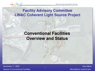
+4º Future FEL Lines +2º +1º +0º SXR -0º HXR -1º -2º -4º Injector Test Facility Limitation of present LCLS Facilities • Up to 6 more undulator branch lines possible at ±1, ±2, and/or ±4 deg. • Existing 3-km SLAC linac can supply 3 different simultaneous 14-GeV, 120-Hz beams or 28-GeV & 14-GeV beams (shared with PEPX). • Can also operate in multi-bunch (~10, 10ns apart) mode to feed FEL farm. • Injector Test Facility will be used to develop source technology, do critical beam physics, and also becomes the electron source for LCLS upgrades. Longer-Term • Possible CW, SC-linac, or compact, high rep-rate X-band linac on SLAC site to feed FEL farm.