
Uploaded by
akiko
0 SLIDES
812 VIEWS
50LIKES
Photometric Image Formation
DESCRIPTION
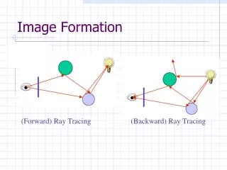
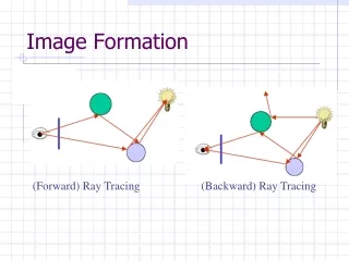
Photometric Image Formation. CSE 559: Computer Vision Guest Lecturer: Austin Abrams. Images / Demo from Steve Seitz, Wikipedia. How are images made?. One half: geometric vision “how the pixel projected onto the image” Today: photometric vision (aka radiometric)
Download

1 / 0
Download Presentation 
Photometric Image Formation
An Image/Link below is provided (as is) to download presentation
Download Policy: Content on the Website is provided to you AS IS for your information and personal use and may not be sold / licensed / shared on other websites without getting consent from its author.
Content is provided to you AS IS for your information and personal use only.
Download presentation by click this link.
While downloading, if for some reason you are not able to download a presentation, the publisher may have deleted the file from their server.
During download, if you can't get a presentation, the file might be deleted by the publisher.
E N D
Presentation Transcript
-
Photometric Image Formation
CSE 559: Computer Vision Guest Lecturer: Austin Abrams Images/Demo from Steve Seitz, Wikipedia - How are images made? One half: geometric vision “how the pixel projected onto the image” Today: photometric vision (aka radiometric) “how the pixel got its color”
- Vision and Graphics Computer Graphics Properties of a scene Image Vision
- Image Formation Approach Come up with a model for how the scene was created Given images, find the most likely properties that fit that model
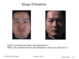
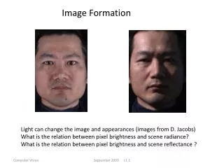
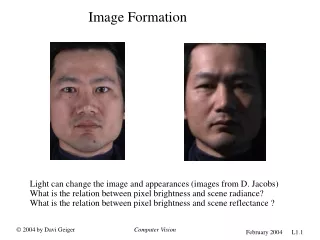
- Diffuse Surfaces Brightness of a pixel depends on: object color lighting direction surface normal But NOT view direction!
- Lambertian Cosine Law The intensity of an observed diffuse object is proportional to the cosine of the angle between the normal and lighting direction I = ρcosθ L θ N = ρ |L||N| cosθ = ρLN
- = L N = L N
- = x I = ρ L N
- Recovering Albedo and Normals Can you decompose a single image into its albedo and normal images?
- x = x x
- Photometric Stereo Given multiple images taken with varying illumination, recover albedo and normals. take pictures in dark room with varying illumination. estimate lighting directions L. recover albedo and normals.
- Side note 1: How to get the lighting direction? Put a shiny sphere in the scene Sphere’s geometry (normals) are known Find specular highlight
- Side-note 2: Why “Stereo”? Surface normals provide constraints on depth differences
- Photometric Stereo If L is known, and albedo is grayscale this is a linear problem. I = ρ(L N) = ρ (Lx Nx + Ly Ny+ LzNz) = Lx Nxρ + Ly Nyρ+ LzNzρ = Lxa + Lyb+ Lzc
- I = ρ(L N) = Lxa+ Lyb+ Lzc For each pixel: Lx1 Ly1 Lz1 Lx2 Ly2 Lz2 Lx3 Ly3 Lz3 … LxnLyn Lzn I1 I2 I3 … In a b c = Then: ρ = sqrt(a2+ b2+ c2) N = (a,b,c) / ρ
- Demo
- When does this model fail? I ≠ ρ (L N)
- Attached shadows L N = 0 L N > 0 L N < 0 I = ρmax(L N, 0)
- Cast Shadows, Ambient Light I = ρ (S L N + a) S = 0 or 1
- Radiometric Camera Calibration Pixel intensities are usually not proportional to the energy that hit the CCD RAW image Published image
- Radiometric Camera Calibration Published f RAW
- Radiometric Camera Calibration Observed = f(RAW) (Grossberg and Nayar) f-1 (Observed) = RAW
- Radiometric Camera Calibration How do you model f-1? f-1(x) =xγ f-1(x) = c0 + c1x + c2x2 + c3x3 + … f-1(x) = f0(x) + f1(x) c1 + f2(x)c2+ … mean camera curve basis camera curves
- Radiometric Camera Calibration I = f(ρ (S L N + a)) Adding exposure: I = f(eρ (S L N + a))
- Heliometric Stereo Given lots of images from a stable webcam, use lighting from the sun to recover: I = f(eρ (S L N + a))
- Heliometric Stereo
- Heliometric Stereo
- Heliometric Stereo


More Related
Audio
Live Player