Download
1 / 26
260 likes | 456 Views
Radiation tolerant fibres for LHC controls and communications. Jochen Kuhnhenn Fraunhofer INT Appelsgarten 2 D-53879 Euskirchen Germany. Outline. Introduction Project overview: "Radiation tolerant fibres for LHC" Results Conclusions. Introduction. Introduction Motivation

E N D
Radiation tolerant fibres for LHC controls and communications • Jochen Kuhnhenn • Fraunhofer INTAppelsgarten 2D-53879 EuskirchenGermany
Outline • Introduction • Project overview: "Radiation tolerant fibres for LHC" • Results • Conclusions
Introduction • Introduction • Motivation • The Fraunhofer Institute at a glance • Radiation effects on optical fibres • Project overview • Results • Conclusions
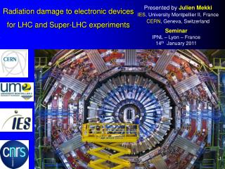
Motivation • More than 1 500 km of optical cables needed for LHC • Control and communication • Beam instrumentation • Advantages of optical communication • Extreme noise immunity and ground potential independence • Lower attenuation (no repeater needed) • Higher flexibility (additional links on demand without tunnel access) • In LHC cleaning insertions IR3 and IR7 high radiation levels expected from day 1 • First tests of installed fibres led to concerns if continuous transmission will be possible (Wijnands et al.: LHC Project Note 351, Presentation at 4th LHC radiation workshop)
The Fraunhofer INT • Experience of more than 30 years on effects of nuclear radiation on electronics and opto-electronics • The institute operates several irradiation facilities(Co-60, 14 MeV neutrons, flash X-Rays, access to 35 MeV protons) • Offering irradiation services to governmental, scientific, and industrial customers including planning and interpretation • Full range of measurement equipment for characterisation and analysis of radiation effects in electronics and opto-electronics • One focus: Radiation effects on optical fibres • Tested several 1 000 fibres of all types and manufacturers • Close contacts to fibre manufacturers and research institutions
Radiation effects on optical fibres • Ionising radiation changes every property of an optical fibre • Refractive index • Bandwidth • Mechanical properties (e.g., tensile strength) • Additional: Generation of luminescence light • These effects show up typically only at relatively high doses or dose rates • Most obvious and disturbing effect is the increase of attenuation
Parameter dependencies of RIA • Manufacturing influences • Fibre type (Single mode, graded index, step index) • Doping of core, doping of cladding (for SM fibres) • Preform manufacturer and used processes • Core material manufacturer • OH Content • Cladding core diameter ratio (CCDR) • Coating material • Drawing conditions • Operation conditions • Wavelength • Light power • Launch conditions • Environment • Total dose • Dose rate • Annealing periods • Temperature
"Radiation tolerant fibres for LHC": Project overview • Introduction • Project overview • Aims • Approach • Experimental details • Results • Conclusions
Project aims • Verification of previous irradiation tests of currently installed optical fibres by Draka • Full characterisation of radiation effects in used Ge-doped Draka fibre • Identification of optical fibres with better radiation resistance • Modelling of radiation induced loss at different dose rates
Project steps • Acquisition of possible alternative optical fibres • Screening test of all samples under identical conditions • Fixed dose, dose rate, temperature, light power, wavelength • Detailed testing of current Draka fibre and best two candidates • Variation of dose rate & dose, wavelength, light power • Accelerated simulation of LHC radiation environment
Experimental details • Screening tests • Dose rate: 0.22 Gy/s • Dose: 10 000 Gy • Room temperature • Wavelength: 1310 nm • Light power: ~ 10 µW • Detailed tests • Dose rate: 0.016 Gy/s 3.7 Gy/s • Dose: up to 150 000 Gy • Wavelengths: 1310 & 1550 nm • Light power: up to 300 µW
Results • Introduction • Project overview • Results • Identification of alternative products • Screening tests of candidates • Detailed testing of now used fibre and best candidates • Modelling of dose rate dependence • Conclusions
Identification of other products • Fraunhofer INT contacted 10 manufacturers known for radiation resistant optical fibres • Of those 6 provided samples • Draka developed new fibre: "Draka New" • Heraeus • Fujikura • Corning • Manufacturer X • Manufacturer Y • Additional sample of current Ge-doped fibre "Draka #445755"
Results of candidate screening test • Logarithmic scale • Linear scale
Draka New better Fujikura better Comparison of dose rate dependence of new fibres • Draka New • Fujikura
Radiation induced loss of used and new fibres: Summary • Results for currently installed Ge-doped fibre by Draka • It is one of the best tested fibres of this type • 1310 nm has advantages for doses higher than 6000 Gy • Increased light power does not improve radiation resistance (not shown in slides) • Two new candidates characterised with focus on dose rate dependence • Both candidates show better radiation tolerance for higher doses • Draka New better at least by a factor of 2 for highest doses • Fujikura better above 10 Gy with best performance (by a factor of 10) between 100 and 1000 Gy
LHC operation conditions assumed for loss modelling • LHC Project Note 375 • One LHC year: 140 days of physics • Assumptions • “Nominal” physics • Fill length + Turn around: 8 + 3 hours • 2.3×10¹⁶ total beam loss per year in IR7 • Dose in fibres ~ 10 000 Gy per 1016 protons(private communication: Wijnands, Kurochkin) • Expected radiation environment for optical fibres in IR7 • Maximum averaged dose per year: ~ 23 000 Gy • Maximum mean dose rate: 2 mGy/s • Peak dose rates expected to be much higher
Accelerated simulation of LHC conditions • Acceleration by factor 10 for 20+10 operation: • Irradiation for 2 hours at ~ 20 mG/s • Annealing for 1 hour • Repeating 10 times • Same dose per cycle (~ 150 Gy) as expected for LHC • Simulates nearly two weeks of LHC operation • Comparison of cyclic irradiation with results of continuous irradiation at corresponding mean dose rate
Conclusions • Introduction • Project overview • Results • Conclusions
Conclusions • Currently installed Ge-doped Draka fibre can be operated for extended time(If average mean dose rate scaling is appropriate) • Both new candidates show better radiation tolerance(Extend depending on dose range) • Cyclic irradiations with annealing periods do not lead to a attenuation increase as the corresponding continuous irradiation • Better understanding of realistic conditions at LHC needs time-dependent dose rate data and further investigations
Thank you very much for your attention • I’m looking forward to your questions … • Contact: Dr. Jochen Kuhnhenn Fraunhofer INT Appelgarten 2 D-53879 Eurkichen Germany Tel.: +49(2251)18200 Fax: +49(2251)18378 Email: kuhnhenn@int.fhg.de