Download

1 / 18
180 likes | 213 Views
CPC undertakes a project to build a Northern LNG Terminal and a 36" offshore gas transmission pipeline from Taichung to Tatan. The design, route, and construction details follow industry standards for safety and efficiency.

E N D
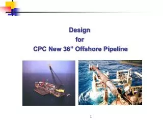
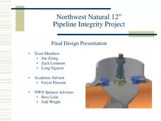
Design for CPC New 36” Offshore Pipeline 1
CPC won the 25 years long term gas supply contract to Tatan power plant in July, 2003 from Tai-Power Company. In order to meet the contract requirements, CPC launched the project to build an Northern LNG Receiving Terminal in Taichung Harbor with a capacity of handling 300 million tonsof imported LNG annually. An associated offshore gas transmission pipeline of 36 inch will be built from Taichung to Tatan. This new offshore pipeline will be integrated with the existing 36 inch offshore pipeline in Tunghsiao Governor Station to constitute a mutual backup system. Tatan Power Plant Tunghsiao 36” existing offshore pipeline New 36” offshore pipeline Taichung terminal 26” onshore trunkline Yung-An Terminal 2
DESIGN CONDITIONS • DESIGN LIFE50 years • CAPACITYTaichung to Tunghsiao - 900 tons/hr • Tunghsiao to Tatan - 600 tons/hr • Max. OPERATING PRESSURE80 kg/cm2 (G) • DESIGN PRESSURE88 kg/cm2 (G) • SIZE OF LINE PIPEID 882.6mm • WALL THICKNESS OF PIPE14.3mm and 15.9mm • MATERIAL OF PIPEAPI 5LX65 • CORROSION ALLOWANCE1.5 mm • Ground Horizontal AccelerationTaichung to Tunghsiao– 0.33g • Tunghsiao to Tatan– 0.23g 3
APPLICABLE CODES • Line Pipe • API 5L “Specification for Line Pipe” • Pipeline Mechanical Design • ASME B31.8“Gas Transmission and Distribution Pipeline System” • API RP 1111“Design, Construction, Operation, and Maintenance of Offshore Hydrocarbon Pipelines” • DNV 1981“Rules for Submarine Pipeline Systems” • Pipeline Offshore Stability • PRCI (AGA) Level 2“Submarine Pipeline On Bottom Stability” • Cathodic Protection • DNV RP F103“Cathodic Protection of Submarine Pipelines by Galvanic Anodes” • Installation Feasibility • DNV 1981“Rules for Submarine Pipeline Systems” 4
PIPELINE ROUTE • Segment 0-1Onshore inside Taichung Harbor • Segment 1Offshore Taichung to Tunghsiao • Segment 0-2 Inside Tunghsiao • & 0-3 Governor Station • Segment 2 Offshore Tunghsiaoto Tatan • Segment 0-4 Onshore in Tatan 大潭 Segment 0-4 Segment 2 Segment 1 Tunghsiao Segment 0-2 & 0-3 Segment 0-1 Taichung 5
PIPELINE ROUTE Segment 0-1 Inside Taichung Harbor • Total Length : • Approx. 5 Km (including 1.1Km HDD section) • Line Pipe Wall Thickness • 15.9 mm. • Construction • HDD for Taichung harbor main channel crossing 6
PIPELINE ROUTE • Segment 1 – Taichung to Tunghsiao 7
PIPELINE ROUTE • Segment 0-2 & 0-3 Onshore Pipeline in Tunghsiao Governor Station Total Length • Approx. 500 m Major Facilities • 2 sets of pig launchers • Metering Station • Filters Integration with Existing Gas Transmission System • Yung Terminal and Northern Terminal can be as the mutual backup system. Segment 0-3 Existing 36”offshore pipeline Tie in Segment0-2 8
PIPELINE ROUTE • Segment 2 – Tunghsiao to Tatan • Total Length : Approx. 85.6Km • Water Depth : 0~86 meters • Sea Bed Soil KP0~0.54 Hard Rock KP1.0~3.0 Soil Liquefaction Area (Due to wave) KP77.9~85.3 Hard Rock 9
PIPELINE ROUTE • Segment 2 – Tunghsiao to Tatan 10
PIPELINE ROUTE • Segment 0-4 Tatan Onshore • Landfall point – 1 Km southern of the inlet of Shin-Wu river. • LFP to Isolation Station – approx. 3 Km. • Isolation station to Metering station – approx. 3 Km. Metering Station Tatan Power Plant Tatan Landfall point Isolation Station 11
BASIC DESIGN • Pipeline Strength Design • Offshore Pipeline Wall Thickness 14.3/15.9 mm • Onshore Pipeline Wall Thickness 15.9/25.4 mm • Buckle Arrestor Wall Thickness 21/24 mm • Corrosion Protection Design • Internal Epoxy coating for 36” line pipe. • FBE or 3-Layer PE external coating. • Installation of Sacrifice Aluminum Anodes for Offshore Pipeline. • Impressed Current CP system for Onshore Pipeline. 12
BASIC DESIGN • On Bottom Stability Analysis • Analysis Software PRCI Stability Software ( Developed by Pipeline Research Council International, Inc) • Analysis Level Level 2 – Simplified Quasi-Static Analysis based on (1) realistic hydrodynamic forces, and (2) realistic pipe embedment calculated by quasi-static simulation of wave induced pipe oscillations. • Two cases of pre-trenching and post-trenching are analyzed. • Environmental Conditions used for Analysis 5-year return period wave and current data used for installation. 100-year return period wave and current data used for operation. • Analysis Result Concrete coating thickness of 65mm, 75mm, 85mm, 95mm,100mm and 120 mm are recommended used in this project. 13
BASIC DESIGN • HDD for Taichung Harbor Channel Crossing Pipeline ID : 882.6 mm Pipe Wall thickness : 15.9 mm External Coating : FBE or 3-Lay PE Concrete Coating Thickness : 61 mm Min. Radius of Curve : 1200 mm Approx. Horizontal Length : 1.1 Km 至通霄 輸氣管線 LNG接收站 Pilot Drilling Reaming Pullback 14
BASIC DESIGN • Pipeline Burial/Protection • Pipeline burial is required throughout. • Burial Depth Offshore : 1 meter cover to top of pipe Shore Approach : 3 meters cover to top of pipe • Post trenching is not allowed in the sand-wave location. • At shore approach and sand wave area, pre-trenching is required. • Natural backfillingis applied in the offshore portion and mechanical backfilling in the shore approach area. 15
BASIC DESIGN • Mitigation Measures for Soil Liquefaction Pipeline route passes through 3soil liquefaction locations, gravel and armor rock cover is the recommended mitigation measure, the EPC contractor may select alternates. • Shore Approach Scour Analysis The results of hydraulic model test by Chung-Kung University indicate that the exposure of buried pipeline of 3 meters cover due to scour will not occur in the shore approach area in Taichung, Tunghsiao and Tatan during service life. 16
BASIC DESIGN • Pre-commissioning • Hydrostatic Pressure Test : Onshore aboveground pipeline : 132 kg/cm2 Onshore underground pipeline : 110 kg/cm2 HDD string : 110 kg/cm2 Offshore pipeline : 110 kg/cm2 • Cleaning : to the level of the volume of received debris less than 5 liters. • Drying : to the level of a dew point below - 20oC. • Nitrogen Purging : to the level of oxygen content less than 2% by volume. 17
END. 18