Download
1 / 51
510 likes | 534 Views
Learn about multitasking and memory management in computer systems, including task switching, memory allocation, and protection mechanisms like hardware modes and privilege levels.

E N D
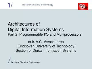
Architectures ofDigital Information SystemsPart 3: Multitasking and Memory Management dr.ir. A.C. VerschuerenEindhoven University of TechnologySection of Digital Information Systems
computer system CPU: 1 processor + memory my program your program (task) (task) device driver operating system (task) disk controller HW interrupt Let’s build a computer...
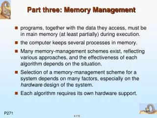
Operating system functions • Maintain a task list (administration) • Know state of all tasks (ready-to-run/waiting/…) • Decide which task must run (task switching) • Manage communication resources • Synchronise communicating tasks • Translate interrupts into task restarts • Allocate and de-allocate memory for tasks
Playing devil (1) Unprotected systems are open to attacks ! • Critical instructions can be executed • 'DI' (disable interrupts) • 'HALT' to crash the whole processor • Hardware ports can be read and written directly • Modify or delete specific files (difficult!) • Format a random track with a single command
Playing devil (2) • Reading / writing of all memory locations possible • Modify O.S. task tables • Kill communication resources • Change another task's data or program (funny) • Fill memory with random data We assume the operating system and device drivers do not allow illegal operations!
Protecting critical operations • Give the processor hardware 'modes' to run in • 'User' mode: critical operations not allowed • 'System' mode: critical operations are permitted • More than two modes possible for ‘fine tuning’ • Switching from system- to user mode need not be protected (we trust the operating system) • Switching the other way around must be protected !
Kernel: PL 0 O.S. core: PL 1 Device drivers: PL 2 User applications: PL 3 Intel 80286: more protection levels • Code access: only in same level or higher levels • Data access: only in same level or lower levels • Stack access: only in same level (separate stacks!) PL:Privilege Level
Switching from user to system mode (1) • Generally done with a kind of software 'interrupt' • Hardware interrupt routines run in system mode too • They need the same mode switching logicbut interrupts remain enabled here • Interrupt routine start addresses in protected table • Not possible to enter system mode at arbitrary address • Called routine is responsible for checking parameters
Switching from user to system mode (2) • The number of ‘software interrupts’ is limited • Signetics 32032 and Zilog Z8000: ONE 'service call' • Other methods exist for protected switching • DEC Alpha: protected library of subroutines • Intel 80286: pseudo segments called ’call gates’
Protecting input/output port access • Declare 'IN' and 'OUT' instructions critical • What to do with the device driver tasks? • Enable and disable access on a per-port basis • Allows fine-tuning of what tasks are allowed to do • Use memory mapped I/O • Let the memory protection handle the I/O protection
Memory read/write protection • Is the hardest of them all to do:There is a lot of it to protect! • Must be combined with memory management • Protection for different access types not enough • Read / Write / Execute (visible on bus system) • Protection for different memory uses is needed • Code / Stack / Constants / Private data / Shared data
'0' Allowed addresses for A program A subroutine X(A) data A accessible by A data X(A) stack A/X(A) same code for shared data A/B accessible by A and B subroutine X ! program B subroutine X(B) data B accessible by B data X(B) Allowed addresses for B stack B/X(B) '-1' The single linear memory space model Where to place the next task?
Linear memory model disadvantages • Needs a 'linking loader’ to modify programs • Programs are loaded into different memory areas each time they are run • Problems with shared subroutine libraries • Inefficient use of memory • Protection must be based on memory areas • Programs are not protected against themselves
'0' '0' program A subroutine X(A) data A data X(A) shared data A/B shared data A/B stack A/X(A) stack A/X(A) '-1' '-1' '0' '0' program B subroutine X(B) data B data X(B) shared data A/B shared data A/B stack B/X(B) stack B/X(B) '-1' '-1' The multiple linear memory spaces model
Multiple linear memory spaces properties • Each program can use the complete memory • More freedom in code/data placement • Higher efficiency by loading once in physical memory • Protects on a 'need-to-know' basis What is invisible cannot be accessed! • Self-protection still difficult (must be address based) • Requires ‘logical’ to ‘physical’ address translation
'0' program A .... .... '0' stack A/X(A) data X(A) .... '-1' A X(A) '0' data A .... '0' '0' shared data A/B subroutine X .... .... '0' program B X(B) .... .... '0' B stack B/X(B) data X(B) .... '-1' '0' data B .... The segmented memory model
Segmented memory properties • Each memory segment in separate address space • Completely avoids the placement problem • Dynamically growing and shrinking memory segments (like stacks) are easy • Protection simple: segment access rights • Address checking is a segment boundary check Segments visible on ‘need to know’ basis • Needs logical to physical address translation
Segmented memory problem • Requires a major ‘philosophical’ change:‘the address’ is split in two parts • A segment identification • An offset within the segment • Automatic segment selection is partially possible • Separate segments for code and stack are obvious • Switching between different data segments requires software intervention!
Address translation • Not needed for linear memory organisation • Processor generated (logical) address real memory (physical) address • May be handy to attach access rights to addresses • Needed for multiple linear address spaces andsegmented memories • Complex for multiple linear address spacesthe actual address must be checked
logical address physical access address rights Table based direct address translation • This table grows very large:Translating 1 million addresses with 4 access rights bits requires a 3 Megabyte table!
logical address '>=' '<' compare compare access physical offset rights Address bounds checking (1) physical address
Address bounds checking (2) • Parallel comparators are VERY expensive • Use a lot of power and chip area • Number of address ranges would be limited • Physical address ranges must have same sizes as the logical address ranges • Memory which is organised into large (undividable) blocks is hard to manage • Same problem in a purely segmented memory
logical address <n> <p> 'page table' logical page offset physical page access <m> <p> rights physical address Paging (1) • <p> bits of the address are not translated: 2p words in a page have the same access rights
Paging (2) • Paging is cheaper than full address translation • Translating 1 million addresses with 1024 word pages requires a page table with only 1024 entries • With 10 bits physical page numbers and 4 access rights bits, the page table takes less than 2048 bytes! • Translating 32 bit addresses with 4096 word pages requires a page table with 1 million entries! • Not all of these pages will be in use at the same time...
Firstlevelpagetable logical address 1st leveltableindex <x> <y> <p> Secondlevelpagetable page offset 2nd level table index Physicalpage 2nd leveltable present <m> <p> physical address access rights Multi-level paging
Multi-level paging example • 4 byte words, 32 bit addresses (2 bits select byte), 1024 word / 4096 byte pages (<p> = 10+2 bits) • Second level table: 1024 entries (<y> = 10 bits) • Entry contains 20 bit physical page number (<m> = 20), leaves 12 bits for access rights if each entry takes one word • Each second level page table fits in one page • First level page table: 1024 entries (<x> = 10 bits) • Entry contains 20 bits physical page number of 2nd level table plus the 'table present bit' - fits easily in one word • First level page table fits in one page
Multi-level paging (continued) • This address translation method is very cheap • The example second level table handles 4 MegaByte • If code, data and stack fit in 8 MegaByte, we need 3 pages (12 KiloBytes) for translation • Multi-level paging is not limited to 2 levels! • Motorola 68020 can go up to FIVE levels of tables • Each table entry (not just the last) can specify access rights, can also give length limit for next table Searching through 5 tables for each memory access is a bit slow
logical address <n> <p> page offset tag '=' compare 'hit!' <m> <p> access rights physical address Speedup: translation lookaside buffer • This 'Content Addressable Memory' lookaside buffer can reach 98% hits with ‘only’ 32 entries
logical address <y> <x> <p> 'tag' 'hit!' physical page access rights <m> <p> physical address A 'set associative' lookaside buffer Cheap, simple RAM
But different translation tags Same line in table The problem with set associative buffers • A ‘tag clash’ makes the lookaside buffer worthless • Two or more different pages used in short loop • With same <y> bits but different <z> (tag) bits 4 bit<z> 4 bit<y> 8 bit<x> ‘WaitHere’ at address 35E6h 35E6 ‘DataPort’ at address 5537h 5537 WaitHere: JNB DataPort.1,WaitHere TWO misses per loop !
logical address Tagtable1 Tagtable2 Pagetable1 Pagetable2 <y> <x> <p> a.r.1 a.r.2 'tag' physicalpage mux mux <m> <p> accessrights physical address hit logic set selection 'hit!' N-way set associative lookaside buffers • Reduce (but do not solve) tag clashes Same hit-rate as‘Content Addressable’
Lookaside buffer replacement strategy • With filled buffer, new translations replace old • With 1-way set associative: <y> bits fix choice! • Best choice: remove one which will not be used • Difficult, but ‘Least Recently Used’ may be the same • LRU requires administration: small choice sets only • Used for N-way set associative lookaside buffers • Another strategy: remove one at random • Works well with large choice sets (CAM buffers!) • Small probability of removing the wrong entry
logical address segment offset Segmentbases Segmentlimits '<'/'>' accessrights error! 'stack' physical address Segmented memory address translation • Segment table is in main memory !
Segmented translation speedup • Processor uses only a few segments at once • Place currently used segment info in on-chip registers • Software decides which segments are loadedno replacement strategy needed in hardware! • Example: Intel 80386 uses 6 current segments • Code, stack and ‘default data’ • Up to 3 ‘extra data’ segments referenced explicitly
Virtual memory (1) • The logically addressable memory size can exceed the physical memory size • Common situation with multiple linear memory spaces • No problem if the actually used amount of memory fits in physical memory • Rely on address translation to 'pack' the memory
Virtual memory (2) • Memory in use > physical memory: problem • Hold part of used memory in physical memory • Store remainder somewhere else, f.i. on a hard disk • Keep this invisible to processor: 'virtual memory' • Hardware stops invalid memory access • Starts routine to move data into physical memory • Then re-tries the failed memory accesswhich may be in the middle of an instruction!
mean stackframe size (z+1: Arrays, Strings) p p p (y-1: PUSH) (y+1: POP) (x+1) last instructionaddress (x) last stackaccess (y) last dataaccess (z) The 'program locality principle' • Consecutive accesses are generally not far apart • The 'working set' contains the active memory areas • Run at full speed if these are kept in real memory!
Virtual memory hardware support bits These work for pages as well as segments • Present bit: in memory if set, otherwise on disk • Processor aborts access if this bit is reset • Accessed bit: set on each read or write access • Detect activity for determining the working set • Written bit: set on each write access • No need to write back to disk if unchanged
A 'swap in' P=1 P=0 A A A A A A 'swap out' A access The ‘working set - clock’ algorithm (1) I need you !
The ‘working set - clock’ algorithm (2) • Swap out writes only if Written bit set • Swap in sets Accessed and Present, resets W • This algorithm is often used (works very well) • Working set pages/segments set A bit a lotthey are not swapped out! • Fair swap out decisions, even under high system load • Will always find something to swap out (robust)
16 K segmented memory 16 K paged memory, 1 K pages ‘0’ ‘0’ 4 K 1.5 K 2 K 1.5 K 3.5 K 3.5 K 3.5 K 1.5 K 4.5 K 2.5 K ‘16’ ‘16’ The fragmentation problem Memory is fragmented inside pages:internal fragmentation Memory is fragmented outside segments:external fragmentation 6 K free, butdoes not fit !! Unusable spaceinside pages !!
Pages versus segments • Fixed-size pages ease swapping to/from disk • Segments provide more complete protection • Intel 80386 uses segmenting AND paging • Protection based upon the segments (done first) • Virtual memory based upon paging (done last) • Two translation steps needed • The P, A and W bits are offered in hardware, managing virtual memory is done in software!
segment number13 bits local/global1 bit 16 bits Intel 80286 example: ‘segment selector’ • Global table with 8192 shared segments • Task-local table with 8192 private segments • 'Requested Privilege Level' allows lowering the protection level of a segment (towards PL 3) 'RPL’2 bits
‘base’24 bits ‘limit’16 bits Present1 bit Accessed1 bit 'PL’2 bits 64 bits Location Size Virtual memory Intel 80286 memory segment descriptor • CODE readable, 'conforming' (for libraries) • DATA writable, stack (reverses limit checking) • TASK STATE (registers, 4 stack pointers, active segs.) • LOCAL TABLE (only in global segment table) Type &access rights No Written bit !
code segmentselector offset16 bits stack copyblock size Present1 bit Intel 80286 calls and jumps • Within same segment only needs offset • Other segment at same PL needs offset & selector • To higher protected code (lower PL) uses 'call gate’ • These are stored in segment tables (‘pseudo-segment’) • CALL instruction points to this ‘pseudo-segment’but the offset in instruction is overruled by call gate • Data copied automatically between stacks 'PL’2 bits
code segmentselector offset16 bits Present1 bit Intel 80286 traps and interrupts • Use 256 entry 'interrupt descriptor table’ • Which contains ‘trap gates’ and ‘interrupt gates’ 'PL’2 bits • These are call gates without stack data copying • An interrupt gate disables interrupts automatically
Intel 80286 I/O protection • Global 'I/O Privilege Level' indicates the highest PL value at which ANY I/O is allowed • Higher PL level code traps on IN & OUT instructions • Each task has a bitmap in the task state segment • Each bit corresponds with an I/O port • Accessing I/O port with bit at 0 generates trap • Size of bitmap variable, undefined ports always trap
task state segmentselector Present1 bit Intel 80286 multitasking support • 'Task state' segments store task information • Special register points to active task state segment • Task switch with JUMP through a 'task gate' 'PL’2 bits PL 0 only:kernel ! 1) Save register set in active task state segment 2) Get address of new task state and declare it active 3) Load register set from this segment, including PC 4) Restart program execution for the new task
'0' 0 1 1 addressspace mux windowselectionregister 'N' windows 1 N - 2 N - 1 '-1' N - 1 N - 1 The old-fashioned way: ‘windowing’ • Selection register is normally an output port • Window selection is part of memory management • Should be managed by operating system! ‘Expanded Memory’
read ROM address: address Read- Only page address Memory register input page write 'core' register data Built-in windowing • Windowing logic can be built inside memory chips • Standard stuff for all kinds of (Flash) ROM’s • Can also save a lot of address pins!