Download
1 / 36
370 likes | 554 Views
ALICE EMCal Electronics. Outline: PHOS Electronics review Design Specifications Why PHOS readout is suitable Necessary differences from PHOS Shaping time / data volume problem EMCal vs PHOS comparison summary. PHOS Electronics,Schematic. One Channel. 32 Channels. 8. 4. Crystal.

E N D
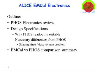
ALICE EMCal Electronics Outline: • PHOS Electronics review • Design Specifications • Why PHOS readout is suitable • Necessary differences from PHOS • Shaping time / data volume problem • EMCal vs PHOS comparison summary
PHOS Electronics,Schematic One Channel 32 Channels 8 4 Crystal APD+PreAmp Transition-card FEE-card w/ ALTRO
PHOS Module Assembly FEE Card 32 Channels 35cm x 21cm 5.5 Watts (170mW/ch) 870SF (27SF/ch)
In total 5 PHOS Modules PHOS Electronics,Schematic 32 Channels 8 4 Crystal APD+PreAmp Transition Card FEE-card w/ ALTRO 14 448 Channels 8 OR Level 0 TRU = Trigger Router Unit Level 1 2 896 Channels RCU = Read-out Control Unit 4 RCU = 1 PHOS Module = 3584 Crystals
Tower/module structure: “shashlik” design Trapezoidal module: transverse size varies in depth from 63x63 to 63x67 mm2 78 layers of 1.6 mm scint/1.6 mm Pb Moliere radius ~ 2 cm Going to Shashlik design allows to use thinner sampling layers to improve intrinsic energy resolution. Pb absorber has dimensions of module Towers defined by smaller optically isolated scintillator tiles Total Pb depth = 124 mm = 22.1 X0 Comparisons: PHOS = 180 mm/8.9 mm = 20.2 X0 ATLAS LiqAr/Pb = 25 X0 CMS PbWO = 25 X0
Use PHOS APD + Charge Sensitive PreAmplifier • Must operate in Magnetic Field. • Need gain (and gain adjustment for trigger) • Light yield from EMCal similar to PHOS
Full Scale energy… inclusive jets 10 Hz @ 50 GeV few x 104/year for ET>150 GeV EFS = 250 GeV (PHOS 80 GeV) From Peter Jacobs
Light yield Light Yield (in photo-electrons) measured at WSU with Cosmic rays in prototype tower using well-calibrated PMT. For APD, with Gain M=1 expect ~2.5 photoelectrons/MeV Compare PHOS: 4.4 pe/MeV @ M=1. For same fullscale signal amplitude MEmcal = 50(MPHOS)*(4.4*80GeV)/(2.5*250GeV)=28
Intrinsic Energy Resolution GEANT Simulation results: • Sampling fraction 8.1% • Intrinsic energy resolution ~12% Calculations by Aleksei Pavlinov
The PHOS APD + CSP Electronic Noise from PHOS Electronics Document • PHOS measurement 625e @ 2ms shaping : 625/(4.4*50)=2.8 MeV • If EMCal uses 100ns shaping, expect ~1500e : 1500/(2.5*50)=12 MeV (36MeV 3x3)
Energy Resolution: All contributions 12% intrinsic 1% calibration Digitization (full scale=250 GeV) PA/shaper eNC=2000 (60MeV) Dual 10-bit ADCs (high and low gain) Even with pessimistic assumptions (eNC=2000) electronics contributions to resolution are unimportant in energy region of primary interest. Important open question: slow neutrons drives choice to investigate short shaping time ~100 ns.
EMCal Resolution: The ALICE “Environment” EMCAL only All ALICE material GEANT Simulations for single photons (i.e. p+p) Significant degradation of resolution A. Pavlinov
The ALICE “Environment” Central HIJING Simulations: Production point of particles with EDeposit Before 30ns After 30 ns Large background from moderately slow neutrons. Calculations by Heather Gray
Soft,Slow (neutron) Background Tower neutron EDeposit Total EMCal EDeposit vs Time Mean neutron EDeposit =36 MeV (i.e. 3 times electronic noise!) with rms=41MeV Note: This is for Central HIJING (worse case, the problem is centrality dependent). Calculations by Heather Gray
Bandwidth: Another shaping time argument • Propose to use tpeak = 100ns with 20MHz sampling • Ex: PHOS Bandwidth • Number of samples = 5*tpeak/Dtsample = 5*4ms/100ns = 200 • Average hit rate (>30MeV) = 200Hz • GTL bus rate = (14FEE)(32chan)(2Gain)(10bit)(200samples)(200Hz)=44.8MB/s • RCU data rate = 2*GTL/RCU partition=89MB/s (limit 100MB/s) • EMCal Bandwidth • Number of samples = 5*tpeak/Dtsample = 5*200ns/50ns = 20 • Average hit rate (>30MeV) = 2000Hz (from 6x6/2x2, or 80% occupancy in central Pb+Pb(GEANT) -> 25% min bias -> 2kHz) • GTL bus rate = (12FEE)(32chan)(2Gain)(10bit)(20samples)(2000Hz)=38.4MB/s • RCU data rate = 2*GTL/RCU partition=77MB/s • If tpeak = 4ms with 200 samples then GTL bus rate=384MB/s - Death!
PHOS vs EMCal Readout comparison • Commonalities: • Same APD + preamplifier • Same GTL bus (but not identical) • ~Same FEE • Same RCU,TRU, etc • Differences • Different T-Card: FEE located far away, need signals driver on T-card+twisted pair • Same FEE but with shorter shaping time, 100ns • Numerology, FEE to GTL to RCU, TRU • New (later option) TRU’ to form larger area energy sums for jet trigger. • Other • Power consumption: 63mW*1152 = 73W in SM, 450W in FEE region of SM
EMCal Electronics: Numerology 32 Channels 8 4 Tower APD+PreAmp Transition Card FEE-card w/ ALTRO 12 36 Level 0 384 Towers 3 OR per SM TRU = Trigger Router Unit Level 1 36 Towers (768 + 384) 13824 Towers TRU’ = Trigger Router Unit’ , . . RCU = Read-out Control Unit Level 1 2(1.5) RCU/SuperModule = 1152 Towers (cf. 896 PHOS)
EMCal Readout Matrix per Supermodule Totals/SuperModule 36 FEE cards 3 GTL bus 3 TRU 1 RCU
PHOS FEE 9 Pre-production prototypes produced at Huaxiang University of science and technology. Used in PHOS test beam period of Oct.’04).
S. Blyth, QM04 EMCAL: main jet physics capabilities • Level 1 trigger for jets, p0/g • essential for jet ET>50 GeV • Improved jet energy resolution • charged-only jets: poor resolution (>50%) • TPC+EMCAL: resolution ~30% • main effect: out-of-cone energy (R~0.3 for heavy ions) • also: intrinsic resolution; missing n, K0L, n • p0/g discrimination to pT~30-40 GeV (cross section limit for g+jet coincidences in acceptance)
Tower granularity (cont’d) Heather Gray, LBNL/Cape Town p0gg opening angle g/p0 shower shape discrimination preliminary p0rejection for pT<~30 GeV/c g p0 More sophisticated SSA underway, possible large improvements Additional g+jet issues: • other backgrounds: fragmentation g, radiative decays, … • isolation cuts g+jet is important but limited measurement • fixed $$$: maximize acceptance for jets, granularity driven by cost
Soft,Slow (neutron) Background Kill the number of neutron hits by tower threshold or (integration) time cut. Tower threshold cut of ~150MeV is effective, but it doesn’t remove neutron energy deposit in tower with real gamma hit! Tower Cut 1 100MeV 2 150MeV 3 200MeV 4 500MeV Time Integ. 0 20ns 1 30ns 2 50ns 3 100ns 4 200ns 5 500ns 6 1000ns Integration time cut can also reduce the number of neutron hits. Benefit also applies to tower with real hit. Note: Using PHOS cluster algorithm without splitting. Calculations by Heather Gray
Soft,Slow (neutron) Background 10-20 GeV/c g + HIJING (b<3fm) Full ALICE Tower energy threshold and integration time cuts are correlated. Shortening integration time allows to lower tower energy resolution, which will improve performance especially at low pT. Note: Using PHOS cluster algorithm without splitting. Feasible to use a shaping time of ~100ns with PHOS electronics? Tower Cut 1 100MeV 2 150MeV 3 200MeV 4 500MeV Time Integ. 0 20ns 1 30ns 2 50ns 3 100ns 4 200ns 5 500ns 6 1000ns Calculations by Heather Gray
Soft,Slow (neutron) Background Taking the shower core only… The Alarming Plot… due to large clusters Conclusion: Neutrons cause large occupancy - difficulty for cluster finding. Will need to use shower core with high tower threshold. Shorter shaping time will improve the situation. Again: This is for Central HIJING (worse case, the problem is centrality dependent). Calculations by Heather Gray
EMCal L0 trigger input concerns… • Upon receipt of L0, the ALTRO chip keeps 14 presamples: • For PHOS with 10MHz sampling this is region of 1.4 ms prior to L0. • For EMCal with 20MHz sampling this is region of 700ns prior to L0. • With ALICE L0 latency of 1.2 ms • For 10MHz sampling this is just okay with ~no presamples • For 20MHz sampling this is 300ns after 200ns peaking time - Death! • Proposed PHOS solution is to use local PHOS L0 trigger output as ALTRO L0 trigger input. Would “solve” problem for EMCal also, but… • This seems to be a very dangerous solution… • L0(PHOS) .ne. L0(CTP): might have L0(CTP) without L0(PHOS) then L2 request when there was no L0… • Danger of filling ALTRO buffer with noisely local L0’s? • Only alternative for EMCal seems to be to keep 10MHz sampling and go to 200ns shaping time.
EMCal Jet Trigger (TRU’?) Conclusion: Increasing trigger region requires in increase trigger threshold for same trigger rejection factor (e.g. central HIJING). Not much difference in trigger efficiency (on PYTHIA jets) versus trigger region size - except for large patch sizes. PHOS TRU size (4x4 tower) works quite well… Calculations by Bill Mayes