Download
1 / 14
140 likes | 301 Views
Computer Architecture and Design ELEC 5200/6200 Class Project Overview. Director: Dr. Vishwani D. Agrawal GTA: Jia Yao (jzy0001@auburn.edu). Outline. The Goal – What are you going to design? The Software The Hardware Evaluation of your project Demo.

E N D
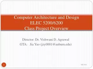
Computer Architecture and DesignELEC 5200/6200Class Project Overview Director: Dr. Vishwani D. Agrawal GTA: Jia Yao (jzy0001@auburn.edu)
Outline • The Goal – What are you going to design? • The Software • The Hardware • Evaluation of your project • Demo
The Goal – What are you going to design? • Design a CPU • basic arithmetic operations: add (+), subtract (-) • basic logical operations: AND, OR, NOT • control flow structures: “if-else” structures, “while” loops and “for” loops • relational operators: ==, !=, >, ≥,<, ≤ • Functions: call and return • Halt Input Control Datapath Memory Central Processing Unit (CPU) or “processor” Output
Jump Shift left2 0 mux 1 4 Add 1 mux 0 ALU Branch opcode MemtoReg CONTROL RegDst zero MemWrite MemRead ALU Instr. mem. PC Reg. File Data mem. 1 mux 0 0 mux 1 1 mux 0 Datapath Example ALU Cont. Sign ext. Shift left 2
PC Altera DE2 Board Download your design and test program What to do on Altera Board: (4) Test and debug the downloaded design (5) Run test programs in a properly working CPU What to do on PC: Design your CPU Simulate your design in Modelsim (3) Synthesize and download your design into Altera Board by Quartus II
CPU design project consists of five parts • Part1 – design an instruction set architecture (ISA): define registers, instruction set • Part2 – design datapath that realizes your ISA: make a choice from single-cycle, multi-cycle or pipeline ? • Part3 – datapath verification: programming and simulation • Part4 – design control unit: based on your choice of datapath • Part5 – hardware implementation and final demo: Altera FPGA board
The Software • Programming: VHDL/Verilog • each component in the datapath is programmed in VHDL/Verilog. • Simulation:Modelsim 6.6b • verification of logic functions. • Hardware implementation: AlteraQuartus II 10.0 • synthesis, timing analysis, design optimization and configuration of Altera FPGA board. * Modelsim and Quartus II are available in Broun 320 Lab
The Hardware • Altera Development and Education Board (DE2) • Control and Datapath: Altera Cyclone II FPGA • Clock: 27 MHz and 50MHz oscillators • Input: Pushbutton switches and toggle switches • Output: LEDs and 7-Segment Displays • Memory: 512 Kbyte SRAM, 8 Mbyte SDRAM, 4 Mbyte Flash Memory; Mega-function Plug-in • Configuring the board in JTAG mode or Active Serial mode
Active Serial Configuration Scheme • “PROG” ON –Configure EPCS16 device by selecting configuration bit stream file (.pof file) in Quartus II Programmer tool. • “RUN” ON – Reset the board; this action cause configuration data in EPCS16 device to be loaded onto the FPGA. • Data is retained in EPCS16 device even when power is turned off; when power is turned back on, data is automatically loaded onto the FPGA.
The Evaluation • A simple test program will be given to you in part 5, and you are encouraged to write your own test program. • Conduct a five-minute demo of the implemented design on your DE2 Board as follows: • Briefly describe the program you will run and the expected results. • Run the program with proper explanation of the buttons you press and results
Demo • Addi $s1, $s1, 2 % $s1=2, $s1 * $s2 = 2 * 4 • Addi $s2, $s2, 3 %$s2=4 • Addi $s6, $s6 7 % $s6=7 • L1: Add $s5, $s5, $s1 %$s5= result of loop of addition • Addi $s2, $s2, -1 % $s2=$s2-1 • Beq $s2, $zero, Exit % if $s2=0, end of loop • Jump L1 % continue loop • Exit: sw $s5, 7($s6) % Memory($s6+7) = $s5 • Halt % program stops
References • Altera Corporation, “Altera DE2 User Manual”, http://www.altera.com/education/univ/materials/boards/de2/unv-de2-board.html • Altera Corporation, “Intruduction to MegaWizard Plug-In”, http://www.altera.com/products/ip/altera/megawizd.html • Auburn University ELEC5200 class website, “Altera Quartus II and DE2 Manual”, http://www.eng.auburn.edu/~vagrawal/COURSE/E6200_Fall10/HW/HW3/Altera%20Quartus%20II%20and%20DE2%20manual.pdf • Auburn University ELEC5200 class website, “Altera Megawizard Plug-In Manager Manual ” • Auburn University ELEC5200 class website, “Run time content editable memory tutorial”, http://www.eng.auburn.edu/~vagrawal/COURSE/E6200_Fall10/HW/HW3/Run_time_content_editable_memory_tutorial.pdf