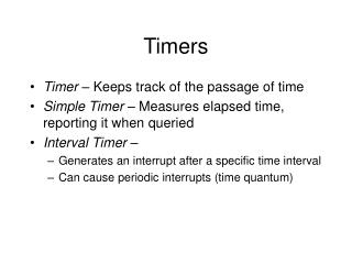
Overview of Timer0, Timer1, Timer2, and Timer3 Modules in Embedded Systems
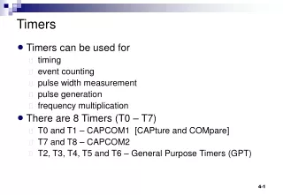
This chapter delves into the Timer0, Timer1, Timer2, and Timer3 modules, detailing their features and operational modes. Timer0 can function as an 8-bit or 16-bit timer/counter with a selectable clock source and prescaler. Timer1 offers 16-bit operations with an interrupt-on-overflow feature and synchronous/asynchronous modes. Timer2 is an 8-bit timer with programmable prescalers and an interrupt function, while Timer3 also provides 16-bit functionality with similar clock source options. Each timer module supports readable and writable registers for enhanced programmability.


Overview of Timer0, Timer1, Timer2, and Timer3 Modules in Embedded Systems
E N D
Presentation Transcript
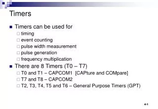
Chapter 7 Timers
TIMER0 MODULE The Timer0 module incorporates the following features: • Software selectable operation as a timer / counter in both 8-bit or 16-bit modes. • Readable and writable registers. • Dedicated 8-bit, software programmable prescaler. • Selectable clock source (internal or external). • Edge select for external clock. • Interrupt-on-overflow.
Timer0 Operation • Timer0 can operate as either a timer or a counter; the mode is selected with the T0CS bit (T0CON<5>). • If the TMR0 register is written to, the increment is inhibited for the following two instruction cycles. • The Counter mode is selected by setting the T0CS bit (= 1). In this mode, Timer0 increments either on every rising or falling edge of pin RA4/T0CKI. • An external clock source can be used to drive Timer0; however, it must meet certain requirements to ensure that the external clock can be synchronized with the internal phase clock (TOSC).
TIMER1 MODULE The Timer1 timer/counter module incorporates these features: • Software selectable operation as a 16-bit timer or counter • Readable and writable 8-bit registers (TMR1H and TMR1L) • Selectable clock source (internal or external) with device clock or Timer1 oscillator internal options • Interrupt-on-overflow • Reset on CCP Special Event Trigger • Device clock status flag (T1RUN)
TIMER1 Operation Timer1 can operate in one of these modes: • Timer • Synchronous Counter • Asynchronous Counter The operating mode is determined by the clock select bit, TMR1CS (T1CON<1>). When Timer1 is enabled, the RC1/T1OSI and RC0/ T1OSO/T13CKI pins become inputs.
TIMER2 MODULE • The Timer2 module timer incorporates the following features: • 8-Bit Timer and Period registers (TMR2 and PR2,respectively) • Readable and writable (both registers) • Software programmable prescaler (1:1, 1:4 and 1:16) • Software programmable postscaler (1:1 through 1:16) • Interrupt on TMR2 to PR2 match • Optional use as the shift clock for the MSSP module
TIMER2 Operation • In normal operation, TMR2 is incremented from 00h on each clock (FOSC/4). The value of TMR2 is compared to that of the Period register, PR2, on each clock cycle. • The TMR2 and PR2 registers are both directly readable and writable. The TMR2 register is cleared on any device Reset, while the PR2 register initializes at FFh. • Both the prescaler and postscaler counters are cleared on the following events: • a write to the TMR2 register • a write to the T2CON register • any device Reset (Power-on Reset, MCLR Reset, • Watchdog Timer Reset or Brown-out Reset) TMR2 is not cleared when T2CON is written.
TIMER3 MODULE • The Timer3 module timer/counter incorporates these features: • Software selectable operation as a 16-bit timer or counter • Readable and writable 8-bit registers (TMR3H and TMR3L) • Selectable clock source (internal or external) with device clock or Timer1 oscillator internal options • Interrupt-on-overflow • Module Reset on CCP Special Event Trigger
TIMER3 Operation Timer3 can operate in one of three modes: • Timer • Synchronous Counter • Asynchronous Counter The operating mode is determined by the clock select bit, TMR3CS (T3CON<1>). When the bit is set, Timer3 increments on every rising edge of the Timer1 external clock input or the Timer1 oscillator, if enabled.