IP Datagrams
IP Datagrams. Lecture 12 November 8, 2000. Frames v. Datagrams. Both provide a clear and concise delineation around the data. Both have a header (and maybe a footer). Frames encompass much smaller amounts of data. RS-232 framing is 5-8 data bits .

IP Datagrams
E N D
Presentation Transcript
IP Datagrams Lecture 12 November 8, 2000
Frames v. Datagrams • Both provide a clear and concise delineation around the data. • Both have a header (and maybe a footer). • Frames encompass much smaller amounts of data. RS-232 framing is 5-8 data bits. • Datagrams are variable length, anywhere from a single octet to 64K octets payload.
Frames v. Datagrams • Frames are media-dependent. Ethernet framing cannot be used on a FDDI network. • Datagrams are media-independent.
Connection v. Connectionless Service • The two can be compared much like P-T-P connections and shared medium connections. • Connection service essentially opens a channel between the two machines and communicates over the channel. • Connectionless service is where data is forwarded from one node to the next. When data reaches the destination, an ACK is sent.
Connection v. Connectionless Service (cont.) • Both models exist with TCP/IP! • Connection service = TCP • Guaranteed delivery • Full duplex communication • Point-to-point communication • Connectionless service = UDP • Unreliable • Non-sequential delivery
Connection v. Connectionless Service (cont.) • IP’s default delivery method is UDP (User Datagram Protocol). • Connection service delivery was an afterthought.
Universal, Virtual Packets • The goal of IP datagrams is to be entirely media-independent. • This independence leads to a universal packet scheme that all IP devices recognize. • The protocol software handles the creation and interpretation of the internet packets. Virtual packets.
IP Datagram • IP datagram = IP packet • Payload (data) is not a fixed size • One octet to 64K octets • Header • Source IP address • Destination IP address • Payload size • CRC • And some other stuff…
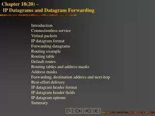
Forwarding a Datagram • Because datagrams are a connectionless communication, they are forwarded from node to node. • At each step, the router (node) inspects the destination address of the datagram and forwards it to the appropriate interface.
Network Address • From our subnetting discussion, we’ve already seen how the network address can be determined from the IP address and the netmask. • 192.4.10.3 & 255.255.255.0 == 192.4.10.0 • With the network address, the router can determine the correct next hop.
Best-Effort Delivery • Although IP makes the best-effort of datagram delivery, it does not guarantee proper handling of: • Datagram duplication • Delayed or out-of-order delivery • Corruption of data • Datagram loss • Other protocol layers are responsible for error handling.
IP Datagram Header (cont.) • Version (4 bits) • Header Length (4 bits) – length of the header in 32 bit words. 5 minimum. • Service Type (8 bits) – Indication of the quality of service desired. • Bits 0-2: Precedence • Bit 3: 0 = Normal Delay, 1 = Low Delay • Bit 4: 0 = Normal Throughput, 1 = High Throughput • Bit 5: 0 = Normal Reliability, 1 = High Reliability • Bits 6-7: Reserved for future use
IP Datagram Header (cont.) • Precedence (from Service Type) • 111: Network control • 110: Internetwork control • 101: CRITIC/ECP • 100: Flash Override • 011: Flash • 010: Immediate • 001: Priority • 000: Routine
IP Datagram Header(cont.) • Total Length (16 bits): Total length of the datagram, measured in octets, including header and data. • Identification (16 bits): A value assigned to aid in assembly of fragments. • Flags (3 bits): Various Control Flags. • Bit 0: Reserved. Must be 0. • Bit 1: (DF) 0 = May Fragment, 1 = Don’t Fragment • Bit 2: (MF) 0 = Last Fragment, 1 = More Fragments • Time to Live (8 bits): Maximum time the datagram is allowed to exist in the system. Each router that handles the datagram decrements the TTL by 1.
IP Datagram Header (cont.) • Fragment Offset (13 bits): Designates where in the datagram a fragment belongs. First fragment is 0. • Protocol (8 bits): Indicates which Transport Layer protocol the datagram is passed to. • Header Checksum (16 bits): Checksum that covers the header only • Source address (32 bits) • Destination address (32 bits) • IP Options (variable): usually don’t appear in datagrams, but must be implemented in IP stacks.
Datagram Transmission • A datagram is an untransmissible unit in itself. • In order for a datagram to be sent across a network, it must be encapsulated into a frame. • Keep in mind, the framing method is media-dependent! • As a datagram traverses the Internet, it remains intact, but the framing around the datagram changes at every node!
Transmission (cont.) • Remember that as a packet traverses a network, the payload remains the same (the datagram), but the framing is created and destroyed at each hop.
MTU & Datagram Size • MTU – Maximum Transmissible Unit • Consider the following example:
MTU & Fragmentation • H1 sending data to H2. • H1’s network allows for 1500 byte transmissions, but H2’s network is only 1000 bytes. • Assuming one 1500 byte transmission, the router will take the 1500 byte datagram, and fragment it into two smaller datagrams, both beneath the 1000 byte MTU restriction in H2’s network. • The fragmentation flags will be set in the datagram header.
Fragment Reassembly • The process of combining all of the datagram fragments is called reassembly. • IP specifies that reassembly is to occur at the destination address! • Advantages: • Intermediate router requires less processing • Routers can send the fragments on to the source, regardless of the path! Routing changes would not disturb the transmission.
Fragment Reassembly (cont.) • In the below example, R2 does not combine fragments, so the datagrams sent onto Net 3 are 1000 bytes, not 1500 bytes!
Fragment Reassembly (cont.) • If one fragment is lost in the transmission, the receiver cannot combine the fragments into the datagram! • The receiver will hold the fragments for a period of time, after which all fragments are discarded. • IP is “all or nothing”. If all fragments aren’t received, the transmission is useless. • TCP v. UDP
Fragmenting a Fragment • Can it be done? You bet. • IP designed such that each time a transmission is fragmented, a new IP header is applied to the subsequent fragments.